Construction
The construction of the demonstration
equipment involves constructing a launch ramp that
allowed for launches at various angles and velocities, modifying a surplus HP
7044A X-Y plotter to act as the ball catcher and
building a digital to analog (D/A) interface between
the computer parallel port and the X/Y inputs on the plotter. The other major
effort is in writing the software to control the demonstration equipment and
display the data for each launch. The Visual Basic code for this is included on
this site and should provide all the functionality needed to demonstrate the
concepts of projectile motion. Also the code is commented to a level that should
make it easy to modify for variations in the demonstration equipment design.
Once you have looked over the construction
details and have a good understanding of how the original project was built the
discussion below will give an appreciation of the relative success of various
parts of the design and might help with possible improvements.
What Worked Well
The components of the project that worked
quite well were :
- Speed gate, consisting of a pair of LED sources and
Photo-Darlington detectors allows accurate speed measurement.
- Parallel port interface, provides a good I/O circuit with
sufficient capacity for the D/A control logic and data input bits.
- Catcher, response time is good and range of motion is adequate.
- Ramp drive, using the plotter Y axis drive and the pulley system
to move the ramp is mechanically effective and gets the "Oh
cool!" response from the class.
- Software, using Visual Basic to manage the demo equipment was a
good trade-off of simplicity and flexibility.
What Might Be Done Differently
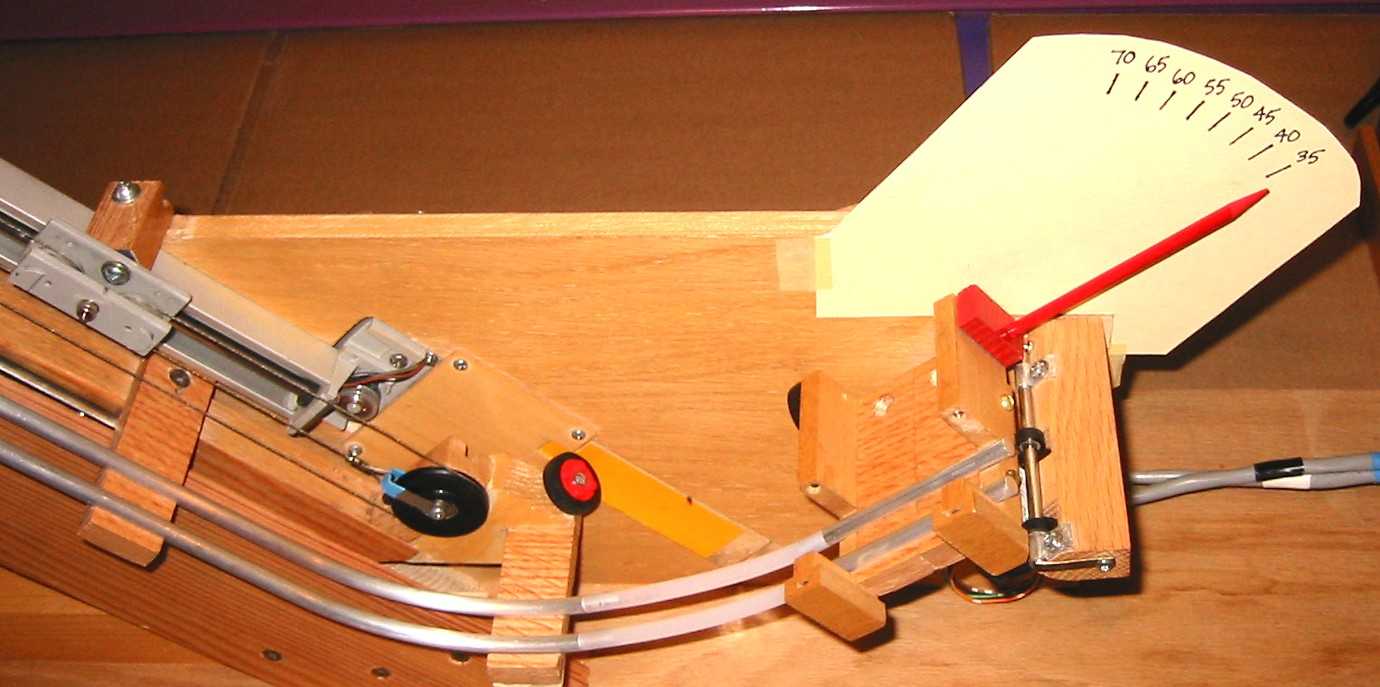 The weak point of the current design is definitely the
area around the adjustable ramp angle. The geometry of this setup only allows a
limited range of launch angles and results in poor stability of the rolling
ball on the lower (curved) portion of the ramp. Because the geometry of the
angle adjustment mechanism (see photo) using the flexible tubing between the
aluminum rail sections is not perfect, warps in the tubing occasionally result
in the ball hitting the speed sensor or bumping off the track entirely. Using a
slightly smaller wooden, plastic or glass ball that will sit slightly lower
between the rails, might increase stability. Alternately, if starting from
scratch, consider using a difference launch mechanism such as a spring or
compressed air.
The weak point of the current design is definitely the
area around the adjustable ramp angle. The geometry of this setup only allows a
limited range of launch angles and results in poor stability of the rolling
ball on the lower (curved) portion of the ramp. Because the geometry of the
angle adjustment mechanism (see photo) using the flexible tubing between the
aluminum rail sections is not perfect, warps in the tubing occasionally result
in the ball hitting the speed sensor or bumping off the track entirely. Using a
slightly smaller wooden, plastic or glass ball that will sit slightly lower
between the rails, might increase stability. Alternately, if starting from
scratch, consider using a difference launch mechanism such as a spring or
compressed air.