 The legend on the right shows what each symbol stands for. A diode
is a component which allows current to pass in one direction only.
The legend on the right shows what each symbol stands for. A diode
is a component which allows current to pass in one direction only.
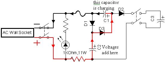
The picture above is a schematic of the power supply. The supply
is actually a voltage tripler. It requires an alternating current
input (from the AC Wall Socket) and outputs three times that voltage as
direct current. Everything inside the thick black box is part of
the power supply.
The legend on the right shows what each symbol stands for. A diode
is a component which allows current to pass in one direction only.
The AC wall socket, as you probably know, is rated at 120V in North
America (240V in Europe). But what you probably don't know is that
number is called the rms (which stands for root mean squared) voltage.
Why's that? Well, since the voltage varies between positive and negative
values 60 times per second (that is the nature of alternating current)
how does one decide which voltage is THE voltage? It keeps changing
all the time! Should one choose the peak voltage? That's not
such a great idea because the peak voltage doesn't represent the entire
signal very well since only a very small fraction of time is spent there.
Most of the time the voltage is either approaching that maximum or receding
from it. To solve this problem the rms voltage was defined.
It is a kind of average. It is the DC voltage that would generate
the same average power as the AC voltage, which turns out to be ![]() .
But let's get to the point: the voltage of an AC socket in a North
American home varies from about -170V to +170V. Therefore the power
supply used in this demonstration can charge the capacitor beyond 360V
(120 times 3). 400V is attained in less than 10 minutes and besides,
going higher than that would be approaching the capacitors maximum rating
of 450V. Operating at its maximum rating would shorten its lifespan.
.
But let's get to the point: the voltage of an AC socket in a North
American home varies from about -170V to +170V. Therefore the power
supply used in this demonstration can charge the capacitor beyond 360V
(120 times 3). 400V is attained in less than 10 minutes and besides,
going higher than that would be approaching the capacitors maximum rating
of 450V. Operating at its maximum rating would shorten its lifespan.
The next three diagrams help explain why this circuit creates a DC output three times greater than the AC input.
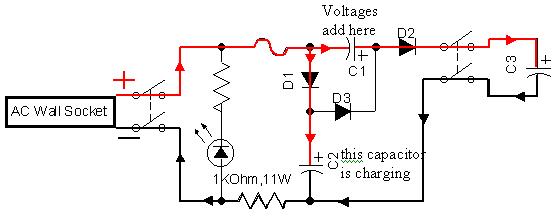
The first diagram below depicts the situation to start with when none of the capacitors have any charge. Let's just suppose that we start with the polarity of the AC Wall Socket arranged as shown. This changes 120 times every second (making 60 complete cycles per second which gives the 60Hz rating with which we are familiar), but let's just consider what's happening during the first 1/120 of a second. Please notice that the capacitors have names C1, C2, and C3, and the diodes are D1, D2, D3. C3 is the large blue capacitor shown in the pictures before which powers the rail gun. In the picture below current travels along the solid red line in the direction shown by arrows from the positive terminal of the wall socket and passes unobstructed through D1 and charges C2 (just like charging a car battery: connect positive of the charger to positive of the battery). The line turns black on the other side of the capacitors just to show which side is positive and which is negative. The capacitances of C1 and C2 are each a mere 50 µF, which means they charge very quickly. 1/120 of a second is more than enough to charge C2 to about 150V. Since C3 is uncharged at this point some current also passes through D3 and D2 to charge C3, though due to its high capacitance of 4.2 mF it still needs a lot more charging.
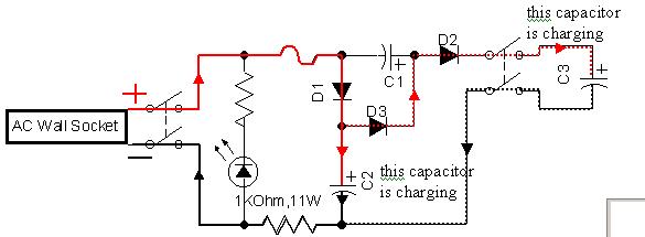
1/120 of a second later the polarity of the wall socket has changed as shown below. We know that C2 was just charged as shown in the above diagram. First let's review what it means to connect two batteries in series, which is to say, when the positive terminal of one is connected to the negative terminal of the other. The voltage between the other two terminals is the sum of each battery voltage. In the picture below we see that C2 is in series with the voltage from the wall socket, and therefore the voltages will add. That's 150V from C2 plus 150V from the wall which charges C1 up to about 300V (it won't really attain that voltage since C2 will discharge so quickly, and in the process drop its voltage so quickly. This is especially true in the beginning when C1 has no charge at all, but let's ignore the messy details :-). It is during this stage that the diodes become especially important. C3 can not discharge because D2 is blocking current from passing that direction. The discharge from C2 must go through D3 since D1 opposes it. This means the total 300V is used to charge C1.
Finally we have the picture below where the 150V from the wall socket is in series with C1 which was just charged to about 300V. Their total voltage is 450V and THAT is the output used to charge C3. Current also passes through D3 until C3 is charged to the wall socket voltage, after which it can only go through C1 as shown. C2 is also being charged at the same time so that when the polarity reverses again we have the picture right above where C2 plus the wall voltage recharges C1. Cycling between this picture and the one above goes on and on until C3 is charged to the desired voltage.