The Construction Details
The Plexiglass Body:
In my original designs, I was hoping to bend a long plexiglass board by heating it up in the main machine shop in the department. However, I was told by the technicians that the 1/2 inch plexglass I had was not going to bend very well. So instead, I took two plexglass boards (each 1 metre long, 20 cm wide, and 1/2 inch thick) and attached them together using steel screws and two aluminum braces. (the braces measure 1m long, 2 inches wide and 1/4 inch thick). The braces were bent at 135 degree angles at both ends and attached to the frame with same 10/32 screws (3/4 inch long)
The Track:
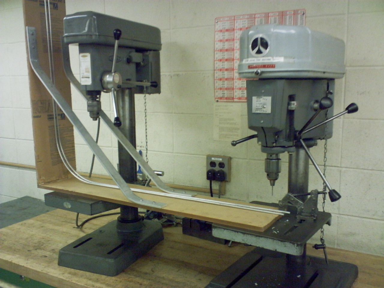
The track for the ball is made of two aluminum rods, each originally 2m long and 1/4 inch in diameter. They are bent 90 degrees in the middle with a radius of curvature of ~13cm. They were then each attached to the body by 8 screws (4/40 thread, 1/2 inch long).
The Track Braces:
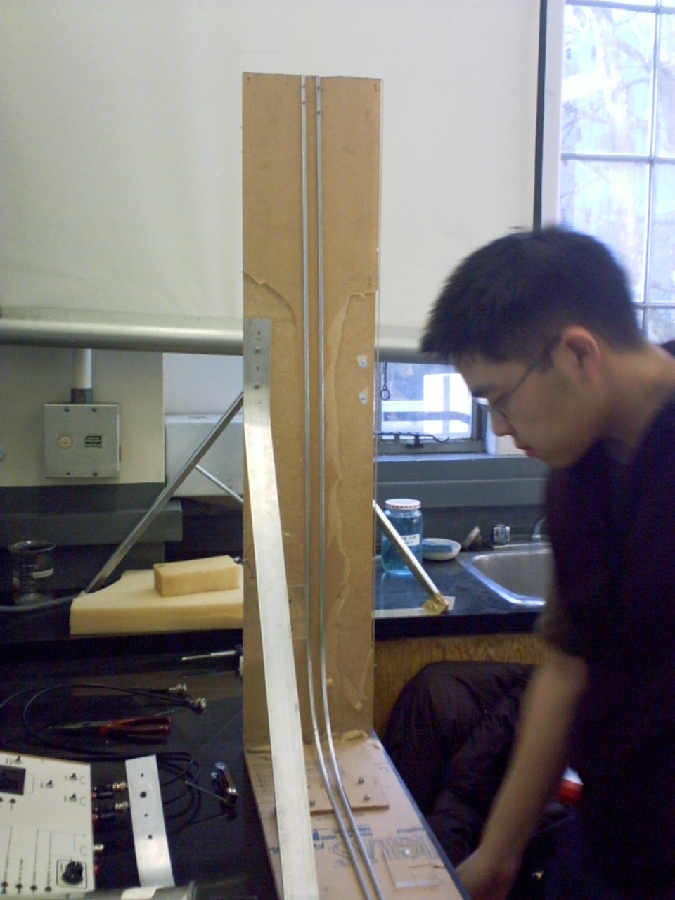
When the marble rolls long the curve in the track (either going up or coming down) the track has a tendency to move apart. In order to keep it from moving too much plexglass braces were attached to the body on the sides of the track. These 4 braces were just small pieces of 1/4 inch thick plexglass strategically positioned near the bend in the track. They are attached to the body with the same screws as before. Several of the braces can be seen below.
The Spring launcher:
The only way to really get the ball high enough, and keep it on the track at the same time, was to build a spring launch at the base. The idea I used for this was the ball launcher on a pinball machine. This is basically an aluminum rod, with a handle on one end, a rubber stopper on the other, and a spring in the middle. The rod slides through a hole in a plexiglass board I attached to the body at the starting point of the track, so when you pull back on the launcher, the spring is compressed. Initially I had difficulty finding the right spring. If the spring was too weak, the ball wouldn't go anywhere. If it was too strong, the plexiglass attached to the body might break. I came across my spring by chance. Someone in the department's main shop just gave it to me for free. I have no idea what the spring constant is for it, so if you want to make this, you'll just have to test different springs.
The Photo gates:
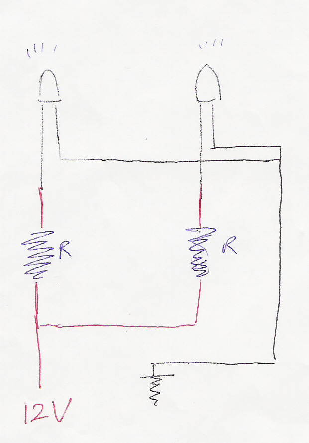
A photogate can give a good approximation to the speed of an object. It works by shining two lights on two detectors separated by some known distance. When the first beam of light is cut, a timer starts. When the second is cut, the timer stops. So if we divide the known distance by the time it took to get from one to the other, we can get the speed. Building it was probably one of the more challenging parts of my demonstration. Each photogate is divided into two, the light part, and the light detector part. For the light part, I used two photo-emitting diodes (Type NSPW500BS) connected in parallel to a 12V source. Each light also has a 430 ohm resistor (R) connected in series. The whole circuit is attached to a 1/2 inch piece of plexiglass such that the lights are separated by 6cm.
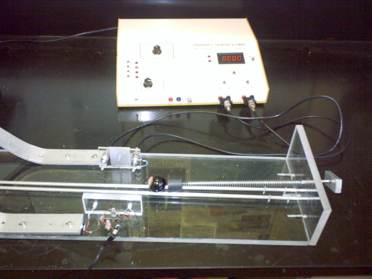
The light detector part is just two photodiode detectors attached to a 1/4 inch thick piece of plexiglass. Although these details appear simple, the challenging part was attaching the gates to the body of the demo. Initially I used a 5 minute epoxy glue. However, as I tested the demo, the ball would continually knock the gates off (regardless of how long I let the epoxy dry). In the end I put a small aluminum brace on the photo detectors and just screwed the light emitters directly to the body. The picture below shows the spring launcher, the light emitters on the bottom, and the detectors hooked up to the time counter.
The finished product can be seen on the Main page.
Back to the Main Page