Figure 1: The Stirling engine and Stirling cycle 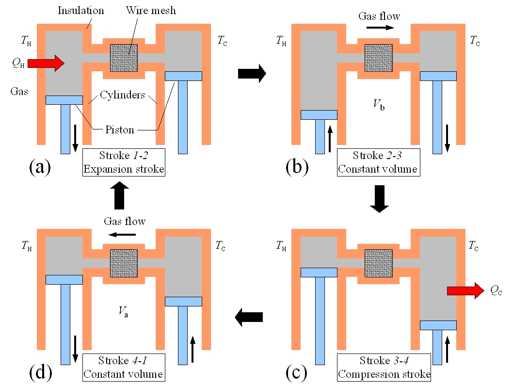
|
The Stirling engine operates by repeatedly completely a sequence of four steps.
Each step in the sequence is reversible and together they form the Stirling cycle. To help understand each of the four steps
in the Stirling cycle consider two piston-cylinder systems whose chambers have been filled with
a gas and are connected by a narrow tube as pictured in Figure 1 to the left.
The left piston is at temperature TH and the right piston is at temperature TC < TH. In the centre of the tube that connects the
two chambers is a wire mesh that will be used to temporarily store heat as described below. For each step in the Stirling cycle the
schematic diagrams of Figure 1 will be mapped to curves on a pressure-volume plot of the Stirling cycle shown in Figure 2. The four steps of the idealized Stirling cycle are:
(a) Stroke 1→2: The gas in the engine is expanded at the constant temperature TH. The left piston moves down and the right piston is fixed. In ordered to maintain a constant temperature the gas must absorb heat QH from the reservoir (Isothermal expansion, path 1→2 in Figure 2).
(b) Stroke 2→3: At constant volume V2, the temperature of the gas is reduced from TH to TC. The gas in the left piston is compressed and the gas in the right piston expanded so that the total volume remains fixed. The hot gas is forced from the left chamber to the right chamber. As the gas passes through the narrow tube it delivers heat Q to the wire mesh. (Constant volume heat removal, path 2→3 in Figure 2)
(c) Stroke 3→4: The gas is compressed at constant temperature TC. The right piston compresses the gas and the left piston is fixed. To maintain a constant temperature the gas releases heat QC to the thermal reservoir at TC. (Isothermal compression, path 3→4 in Figure 2).
(d) Stroke 4→1: At constant volume V1, the temperature of the gas is increased from TC to TH. The gas in the left piston is expanded and the gas in the right piston is compressed so that the total volume remains fixed. The cold gas is forced from the right chamber to the left chamber. As the gas passes through the narrow tube it recovers the heat Q stored in the hot wire mesh. (Constant volume heating, path 4→1 in Figure 2).
|
Figure 2: The Stirling cycle PV-diagram 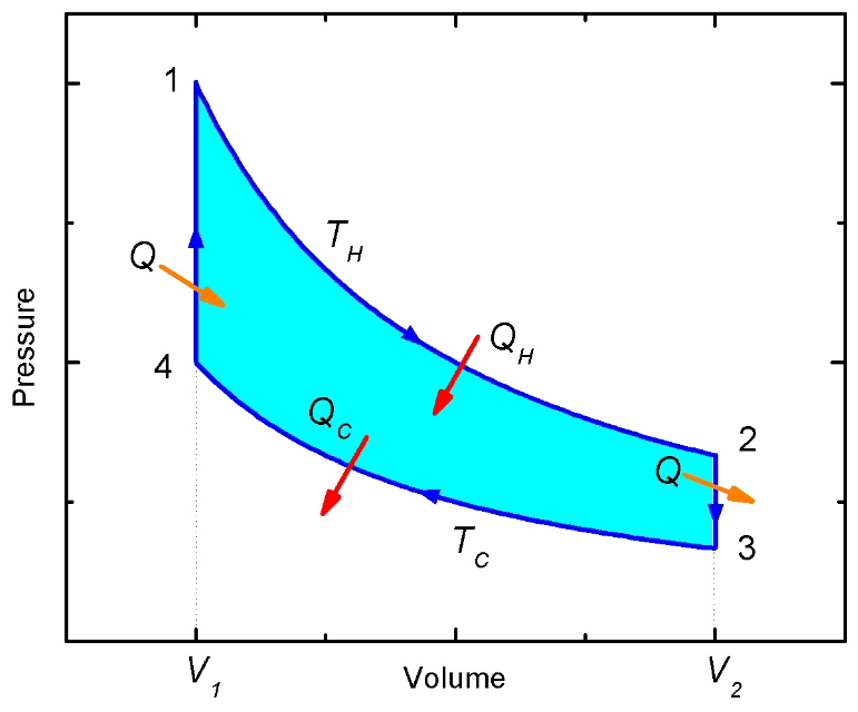
|
|
Figure 3: Displacer-type Stirling cycle 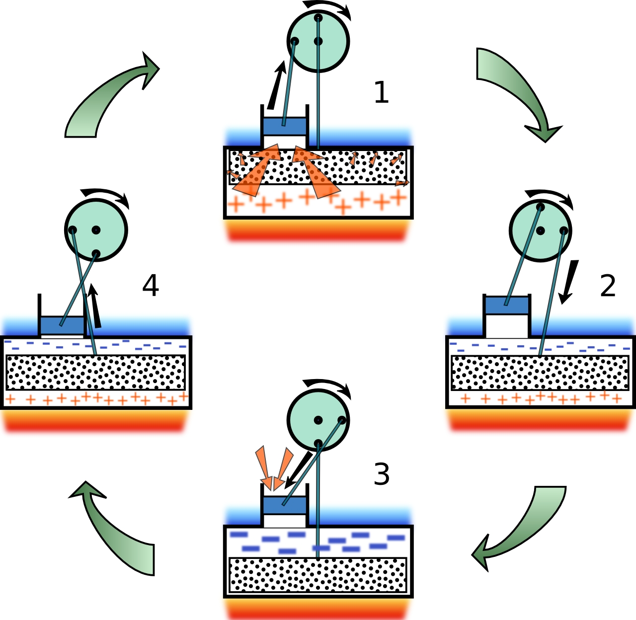 This great picture was taken from this site. |
Figure 3 schematically shows the operation of a practical (and commercially available) Stirling engine at various stages of the Stirling cycle.
In any real Stirling engine the idealized Stirling cycle cannot be achieved. The four steps are blurred together and the cycle on a PV-diagram
appears elliptical. This displacer-style Stirling engine is the type purchased, modified, and then demonstrated here.
This type of engine has one small sealed piston, called the power piston, and one larger loose fitting displacer piston. The role of the displacer
piston is simply to move, or displace, working gas in the engine back and forth between a heated lower region and the upper cooled region.
In the design pictured in Figure 3, the lower plate is heated with a flame and the upper plate is cooled by water or the ambient surroundings.
The two pistons and linked together such that their movements are 90o out of phase. That is, when the power piston is either at its maximum
or minimum height and moving slowly, the displacer piston is at its halfway point and moving at its maximum speed.
At position 1 of Figure 3,
the displacer piston is in the upper cold region which forces the working gas to occupy the hot region and be at temperature TH. Heat is added
to the gas and it expands forcing the power piston to move upwards (path 1→2 in Figure 2).
At position 2 the power piston is at its maximum
height (the gas has its maximum volume V2) and is moving very slowly approximating the constant volume path 2→3 in Figure 2. The displacer,
on the other hand, is moving into the hot region causing the gas to move to the cold region. In this design, the displacer itself plays the role of
the wire mesh of Figure 1 by temporarily storing energy taken from the gas as it cools from TH to TC.
At position 3, because all of the gas
is in the cold region, it contracts (heat is removed from the gas) causing the power piston to slide down (path 3→4 in Figure 2).
At position 4,
the power piston is at its minimum volume V1 and is moving slowly. The displacer piston is moving upwards forcing the gas into
the hot region. As the cool gas passes by the displacer it recovers the heat that was temporarily stored in the displacer (path 4→1 in Figure 2).
At the completion of this process the state of the Stirling engine returns to 1 and the cycle repeats indefinitely.
|