This demonstration is aimed toward an audience of eleventh and twelveth grade physics students. Each student should have a preliminary understanding of the common forms of energy in a system. Although useful, a background of thermodynamics is not necessary. It is important to maximize student participation to allow independent critical analysis. Hopefully the student will walk away with an intuitive grasp of how to analyze energy exchange in physical systems and much less fear in seeing the world in a physical/mathematical perspective.
The goal of this presentation is to expose the students to the kinetics and thermodynamics of an heat engine under simple, ideal, and realistic scenarios.
The students should be guided through the derivation of the theoretical maximum efficiency of an heat engine and then a Fermi-style calculation of the efficiency of an real heat engine; the Stirling engine. Within this process, the First and Second laws of Thermodynamics along with heat capacity and rotational kinetic energy equation should be introduced and utilized. The students should be surprised at the discrepencies between the ideal and realistic results.
Lastly, the operation and functionality of the Stirling engine should be covered. It is not necessary for students to memorize any equations in this presentation, but should aim for an intuitive grasp.
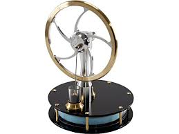
Pre-built Stirling Engine
To purchase a pre-built Stirling engine to use in the demonstration, follow this link or search for a displacer-type Stirling engine on Amazon.
Pre-built Presentation Powerpoint
If embedded PDF is not working click here to download PDF
4. Silicon sealant or double sided foam tape (thick)
5. Steel wire wool
6. Fishing line
7. Sandpaper
8. 18 gauge steel wire (around 1.5 mm)
9. 24 gauge steel wire (around 0.6 mm)
10. CD
11. Bottle cap (from sports drink or water)
12. balloon (12 inch)
13. #8-12 bolt, nut, and 2 washers (any small screw will work)
14. A small piece of thin rubber for an extra seal if necessary
Tools Required
1. Can operner
2. Exacto knife (or sharp cutting blade)
3. Scissors (or tin snips)
4. Thumb tack
5. Plyers
6. Wire cutters
7. Candle
8. Hot glue and hot glue gun
9. Needle if necessary
Procedure
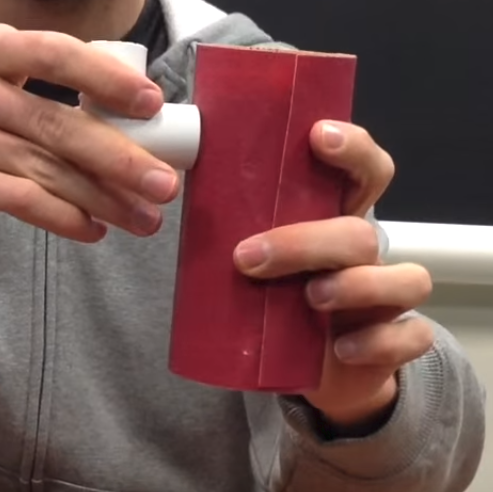
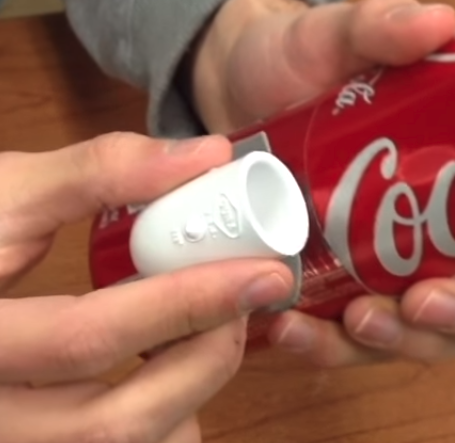
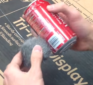
1. Wrap sand paper around the full can of soda and vertically grind the PVC elbow until the groove fits well around the soda can. We'll need the PVC elbow to fit air tight so try to shape the groove properly as much as possible.
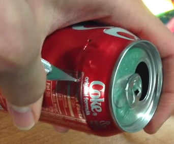
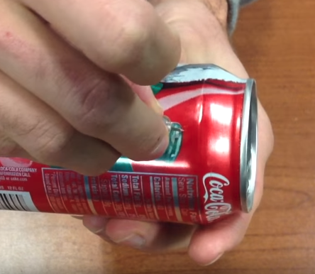
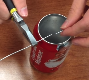
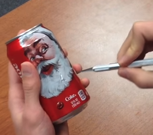
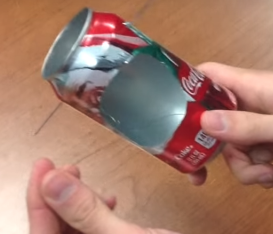
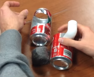
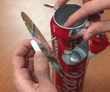
2. Using the exacto knife, cut off the top of the empty soda can. Try to make the edge as smooth as possible. If necessary, cut jagged edges off with scissors or tin snips. See image for details.
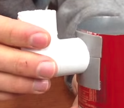
3. Using either the double sided foam tape or the silicon sealant, attach the grooved PVC elbow near the top open side of the empty soda can. Make sure the PVC elbow retains a hole for air to flow through. The full soda can should be used as leverage for an air tight seal.
4. Cut a hole on the inside of the empty soda can where the PVC elbow is attached. Make sure to not cut the hole larger than the circular PVC opening.
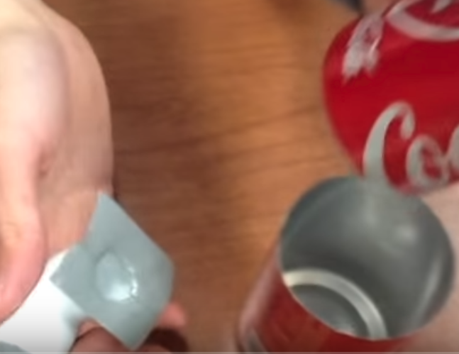
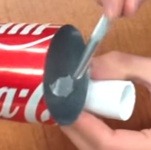
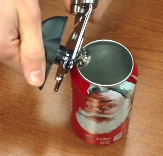
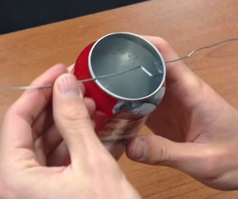
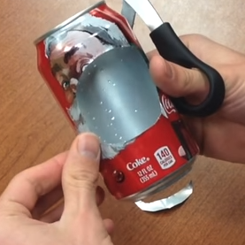
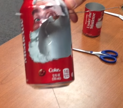
5. Using a can opener, cut off the lid of another empty soda can.
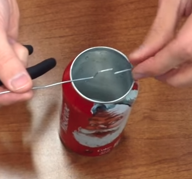
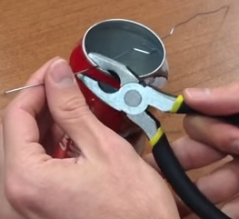
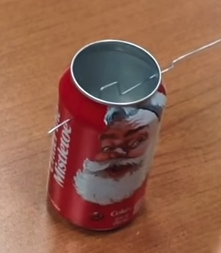
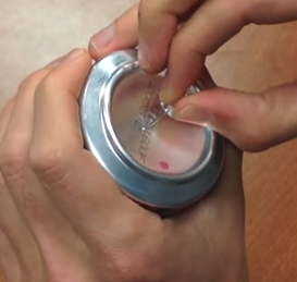
6. Using a thumb tack, poke a hole near the open end of the de-lidded soda can and do the same on the opposite side; making sure that the holes have symmetrical positioning. These holes will hold the crank shaft of this engine in place.
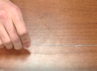
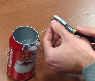
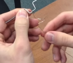
7. To construct the crankshaft, cut about a foot length of the 18 gauge wire and make sure it is as straight as possible.
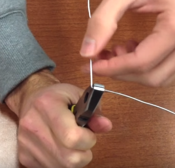
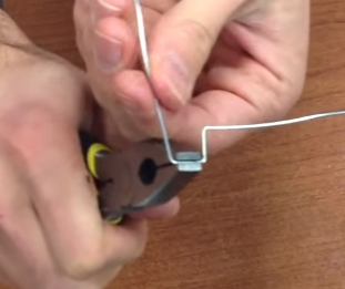
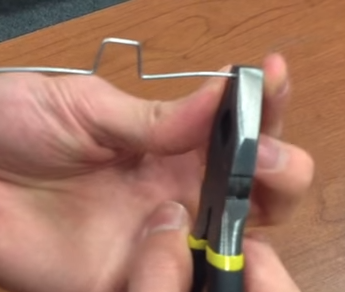
8. Using pliers as leverage, make a 90 degree bend at around half the length of the 18 gauge wire.
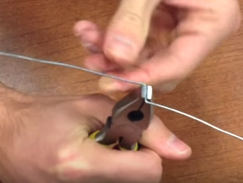
9. Using pliers as leverage, make a 90 degree bend next to the first bend on the longer side of the wire. The distance from the first bend to the second bend should be approximately one third of an inch; although it is not important to be length precise, it is important to make sure the bends are symmetrical to the other on the opposite side.
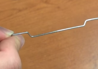
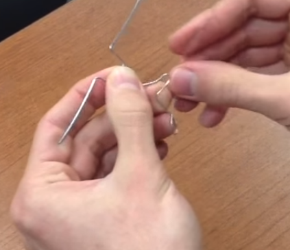
10. Approximately half an inch next to the previous bend, make a another 90 degree bend.
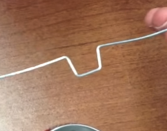
11. Approximately one third inch next to the previous bend, make another 90 degree bend. The end result should be approximately a U shape
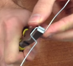
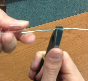
12. Align the U shape to the center of the de-lidded can. Grab the crank shaft with your pliers next to the outer edge of the can and bend at a 45 degree angle in the direction perpendicular to the U.
13. Approximately one sixth of an inch next to the 45 degree bend, use your pliers to bend the wire 45 degrees back into the original direction.
14. Insert and maneuver the 45 degree bended side of the crank shaft into one of the holes of the de-lidded can from the inside to the outside.
15. In order to insert the other side of the crank shaft into the opposite hole, cut the excess until it can be maneuvered in.
16. On the 45 degree bended side of the crank shaft, cut off the excess wire at approximately the half way point between the bend and the end.
17. Remove the crank shaft from the de-lidded can for now. Use a sharp blade to cut a large hole from one of the faces of the de-lidded can. The hole should be facing the crank shaft. The purpose of the hole is to allow us to attach the fishing line from crank shaft to the displacer. The size of the hole doesn't matter as long as you can reach your hand in there to do the work.
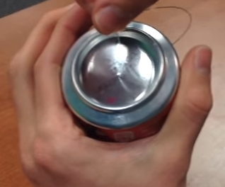
18. On the bottom of the de-lidded can, use a thumb tack to make a very small puncture through the center for the fishing line. It is very important that the size of this hole is as small as possible. If it is too large then the can containing the displacer will not be airtight and the engine will not work. If necessary, cover the hole with a thin piece of rubber and seal with hot glue, then use a needle to thread fishing line through.
19. Push or thread the fishing line through the bottom of the hole you've just made.
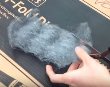
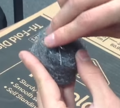
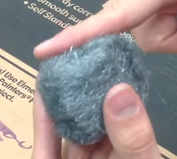
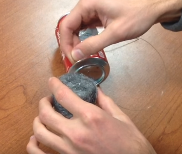
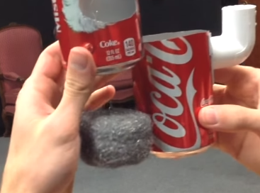
20. To make the displacer, unroll and flatten the steel wool. The goal is to create a steel wool cylinder with the height of approximately one third of the height of the empty soda can where the top was cup off; i.e. the one attached to the PVC elbow. Cut the steel wool with scissors or tin snips if necessary.
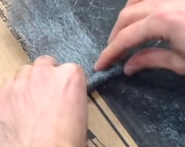
21. Cut approximately a foot of the 24 gauge steel wire and place on top of the unrolled steel wool. Tightly roll the steel wool around the steel wire.
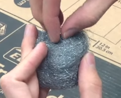
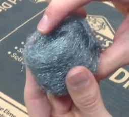
22. Keep wrapping layers of steel wool around until the diameter of the cylinder is 1 or 2 centimeters less than the diameter of the de-topped empty can. It is important for the air to flow around the displacer but not through it.
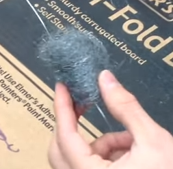
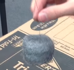
23. Smooth out the cylinder with your hands or scissors and then twist one end of the steel wire around the bottom of the steel wool so that it can be held up by the other end.
24. On the other side of the steel wire, we need to create a hook for the fishing line to attach to. Cut and leave one inch of wire coming out of the steel wool and bend the wire into the wool. Push the hook into the wool so that only a little bit of the hook is sticking out.
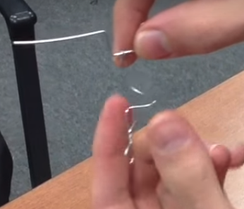
25. Cut a piece of 24 gauge steel wire and wrap one end around the U of the crank shaft. Around the middle of the length of the 24 gauge wire, allow it to fold a bit so that you can make adjustments to the total length if necessary. If the 24 gauge wire is too loosely wrapped then consider making the attached end into an U shape so that it does not jiggle side to side during operation.
26. Make a hook at the bottom of the 24 gauge steel wire by twisting and cutting off the excess wire.
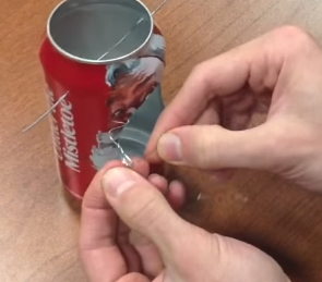
27. Fit the crank shaft back into the de-lidded can and thread the fishing line through the bottom hole which you've already made. Tie the fishing line to the hook you've made in the previous step.
28. Tie the other end of the fishing line to the hook on the displacer. By placing the de-topped can next to the bottom of the de-lidded can, adjust the height of the displacer until it is approximately 1 cm away from touching the bottom. Cut off any excess string.
29. Press the de-topped can onto the bottom of the de-lidded can. It is important that there are no leaks between the top and bottom cans. If the cans do not fit together to make an airtight seal then use hot glue.
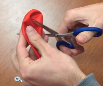
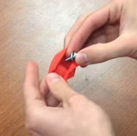
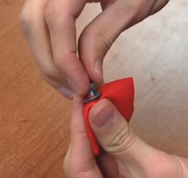
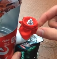
30. To seal the open end of the PVC elbow, cut the balloon in half horizontally. Place a washer on a screw and press the screw into the center of the balloon. Use a knife to help the screw pierce the center of the balloon.
31. Place a washer on the screw and screw the nut into place for an airtight seal.
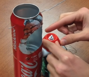
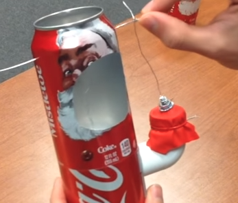
32. Place the balloon on the open end of the PVC elbow with the thread of the screw facing up. Wrap a rubber band or steel wire tightly around the balloon to make an airtight seal.
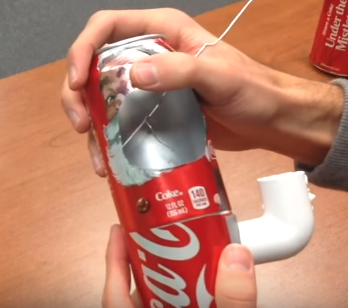
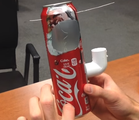
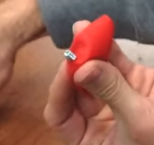
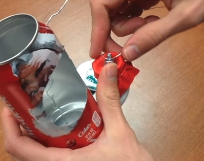
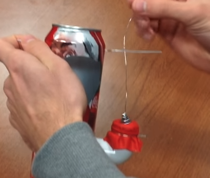
33. To connect the crank shaft to the piston, cut a piece of 24 gauge steel wire and wrap one end around the thread of the screw. Wrap the other end around the crank shaft making sure that it is wrapped past the 45 degree bends. During a full rotation of the crank shaft, the balloon should not be stretched too much. Make sure the length of the wire allows the piston to expand and fall smoothly without excessive tension. The third image below illustrates the maximum tension the balloon should experience. Cut any excess wire.
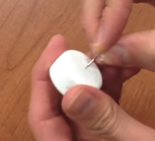
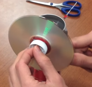
34. To construct the flywheel, push a thumb tack through the center of a bottle cap making a hole that can fit the crank shaft.
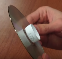
35. Tape or hot glue the flat side of the bottle cap to the center of a CD.
36. Push the short end of the crank shaft through the hole in the bottle cap and hot glue the crank shaft to the bottle cap. Tape is also an option to make the crank shaft and the fly wheel into one unit.
37. Place Stirling engine over lit candle and wait for ~20 seconds. Give the crankshaft some initial momentum by spinning it with your hand and the engine should sustain operation; shown in the video.
Tips if engine is not functioning properly.
Check the crank shaft or connecting rod for any defects causing a rough rotation.
Make sure balloon is not pulled or pushed too tight during rotation.
Check for any air leaks from the bottom can.
Make sure the hole in between the top and bottom cans containing the fishing line is not too big or leaking.
Check that the displacer is not hitting the bottom of the can. There must be a little room underneath it.
Make sure the steel wool is moving freely and not snagging onto any part.
Some photos and information used in these instructions were borrowed from Joshua Zonker's Youtube channel. For his video tutorial of how to build a soda can Stirling engine click here.