This demo was built as part of PHYS 420C for demonstration of concepts in Physics. The demo is targeted at grade 11-12 students in BC curriculums who will have had exposures to electromagnetic waves and its properties, along with behaviors such as interference and diffraction. These concepts, however, tend to remain theoretical and hard to visualize for students. This demo aims to give students a chance to see these concepts along with their applications in action.
By the end of the demo, students will understand how interference plays into the formation of diffraction patterns, as well as apply this understanding to Bragg's diffraction. They will have worked through simple derivations of the law, made predictions of angles of maxima, and confirm said predictions with the demo.
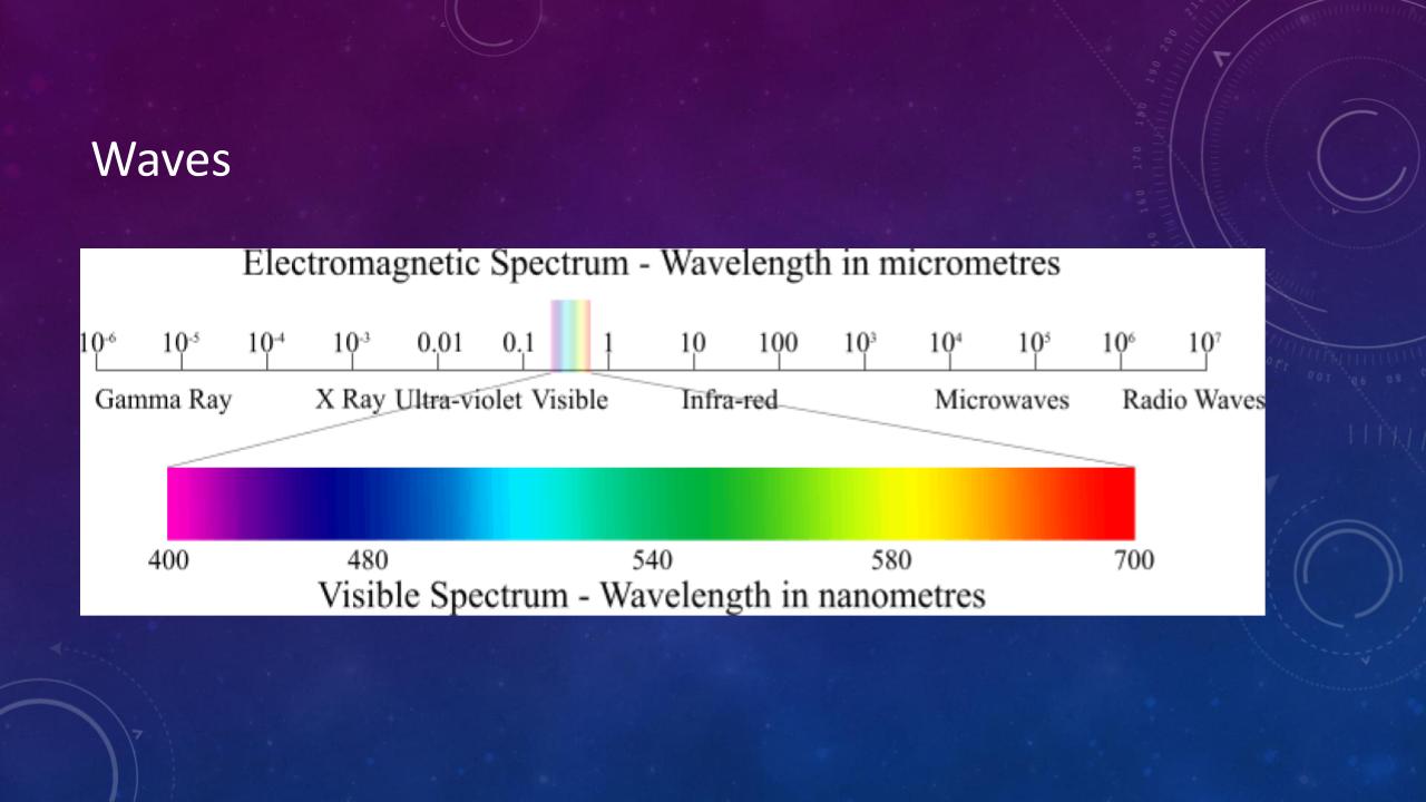
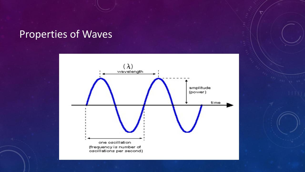
First, the concept of waves and their respective properties such as amplitude, frequency and wavelength will be quickly explained if the students have not covered this material.
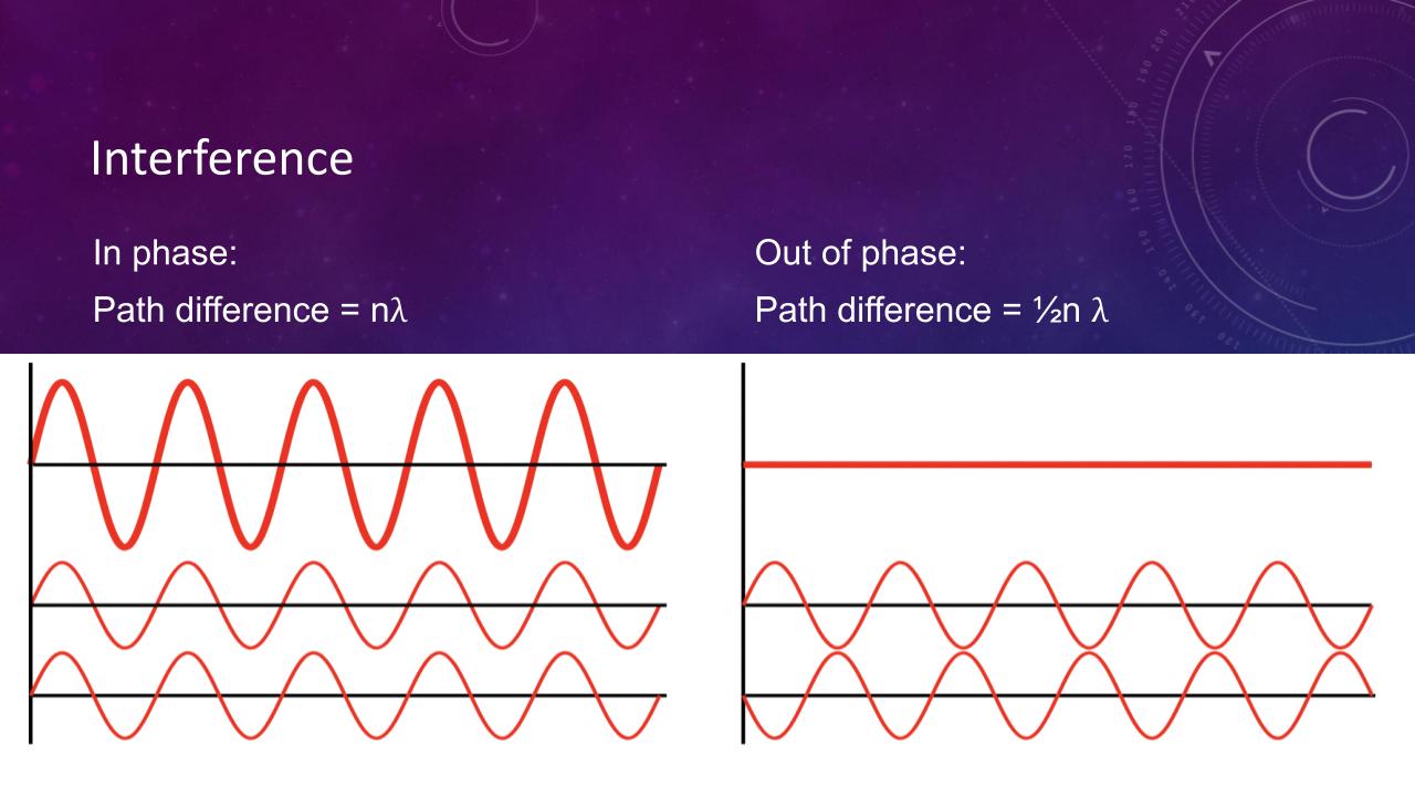
When two waves come close to one another, their effects add together or “superpose” to form a resultant wave of greater, lower, or the same amplitude. This is called interference. Constructive and destructive interference result from the interaction of waves that are correlated or coherent with each other, either because they come from the same source or because they have the same or nearly the same frequency. Constructive interference happens when waves are “in phase”, whereas destructive interference happens when waves are completely out of phase, meaning path difference is exactly half the wavelength. Diagrams of constructive and destructive interference will be shown to explain this concept more clearly.
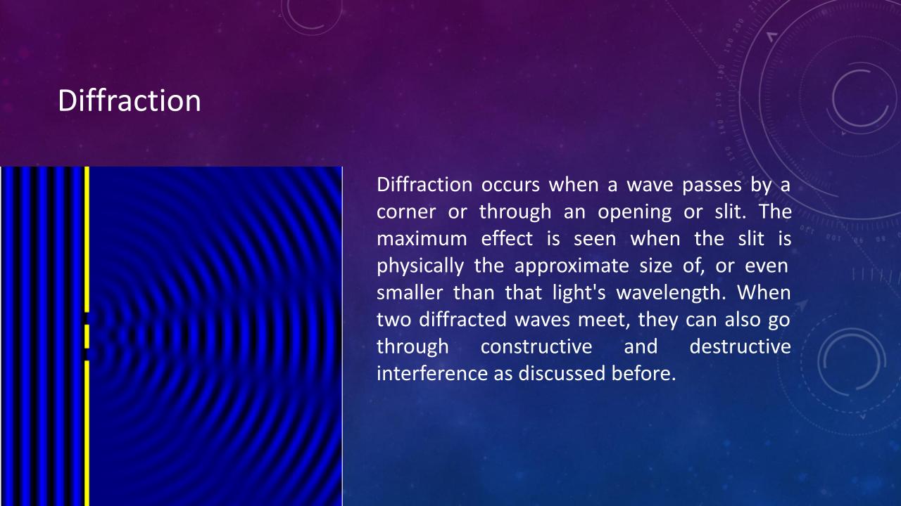
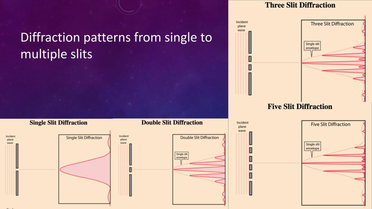
Diffraction of light occurs when a wave passes by a corner or through an opening or slit. The maximum effect is seen when the slit is physically the approximate size of, or even smaller than that light's wavelength. When two diffracted waves meet, they can also go through constructive and destructive interference as discussed above. Images of diffraction of waves through openings will be provided. Double slit and multi-slit diffraction of light and diffraction in water waves will also be provided so that such diffraction patterns can be demonstrated.
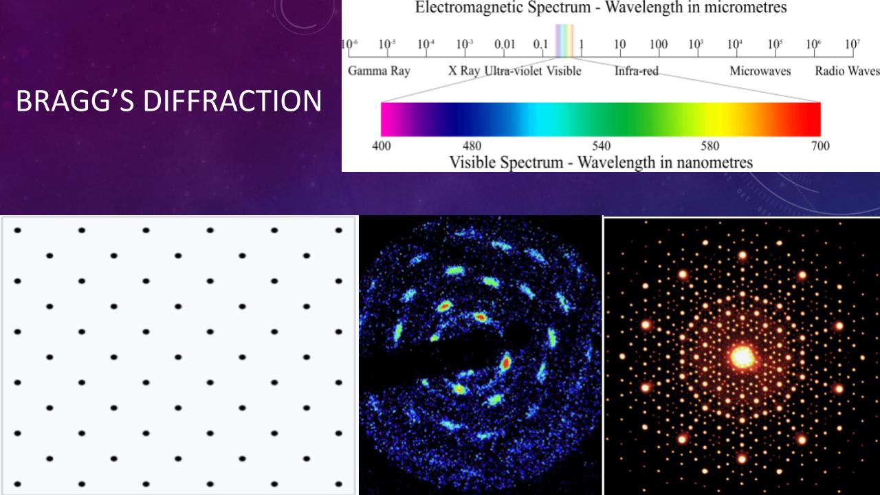
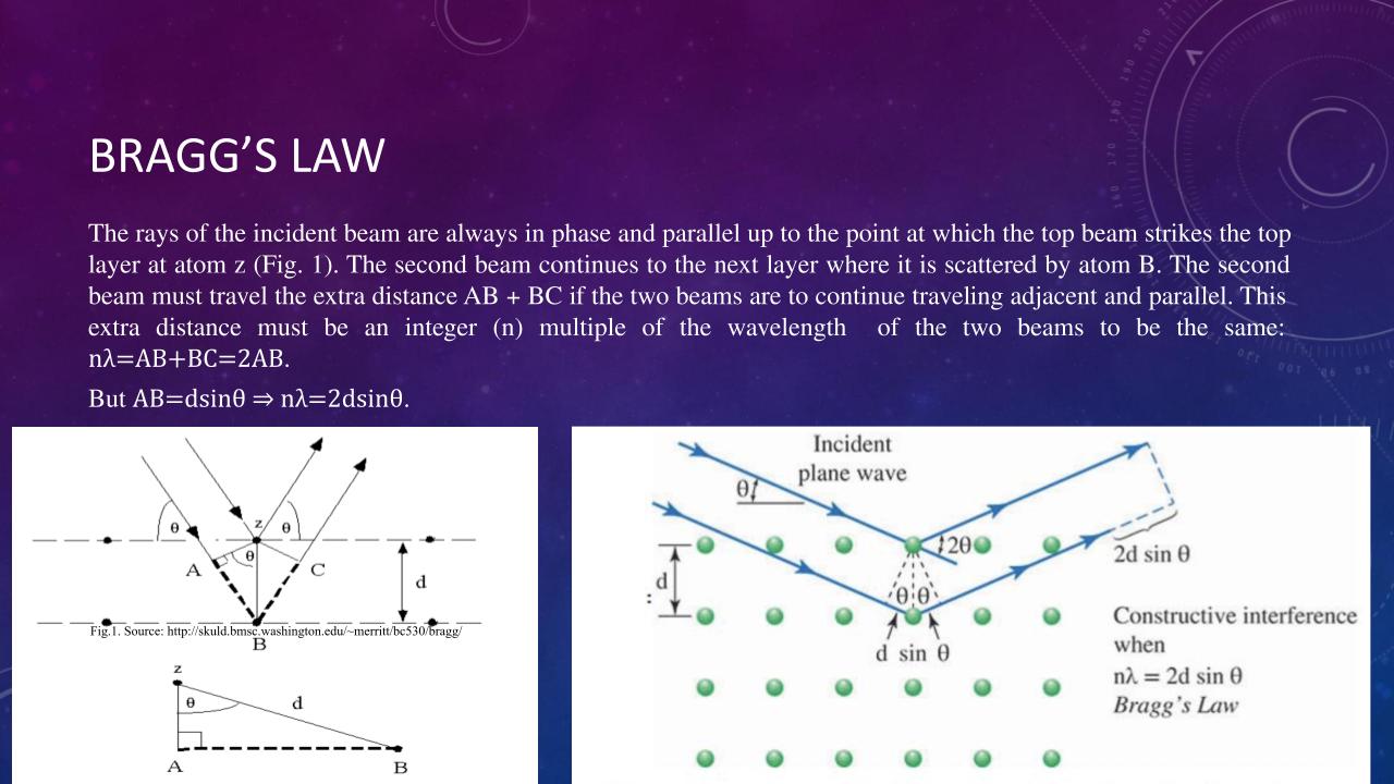
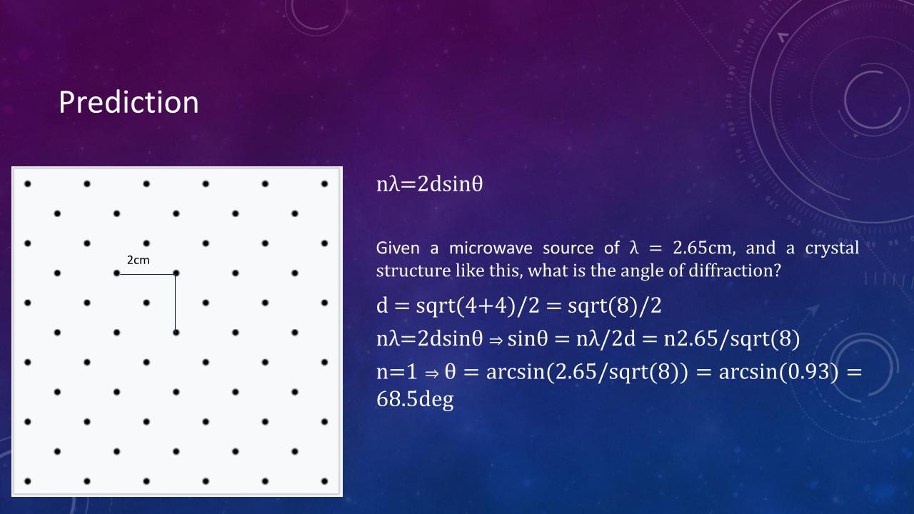
Bragg’s Law provides the angle for diffraction patterns that occurs when electromagnetic radiation, with a wavelength comparable to atomic spacing, is scattered by the atoms of a crystalline system, and undergoes constructive interference. In this case, the atomic spacing acts in a fashion similar to diffraction gratings. The derivation will be detailed in the presentation, with a check on understanding by making the students derive this in their own worksheets with guided instructions.
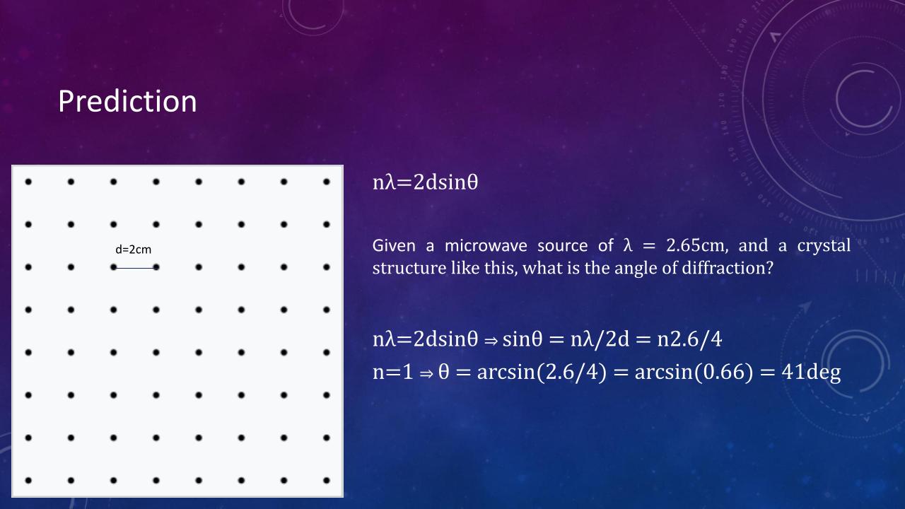
It’ll be explained to the students that Bragg’s diffraction is used to investigate crystal structures with atomic spacing typically in Å scale, which means X-ray radiation are most common in such experiments. However, both the X-ray and crystal structures are not visible to the eye; therefore, for demonstration purpose, a lattice model will be used, which will require microwave radiation with approximately similar wavelength (mm-cm range). It should be explained that a 2D model is used as it is most easily constructed and tested. Limitation includes the range of motion of the transmitter/detetor, as well as the radiation intensity which might be too low to be detected with available equipment on 3D models. Students will then be able to make predictions of where the diffraction maxima/minima are based on spacing of lattice model. Theory will be tested through demonstration. This will be repeated with other lattice structures available.
X-ray diffraction has wide and various applications in the chemical, biochemical, physical, and material sciences. X-ray diffraction has been used for the identification of antibiotic drugs, which has a unique X-Ray Diffraction (XRD) pattern that makes their identification possible. It is also used in crystallography to identify different properties of crystals and chemicals. Due to neutron’s magnetic moments, neutron scattering allows for the study of properties of metal materials and has application in analyzing stresses in aerospace and automotive components. Bragg’s diffraction also has applications in medical imaging such as X-ray/CT scans.
- ~11GHz microwave transmitter and receiver
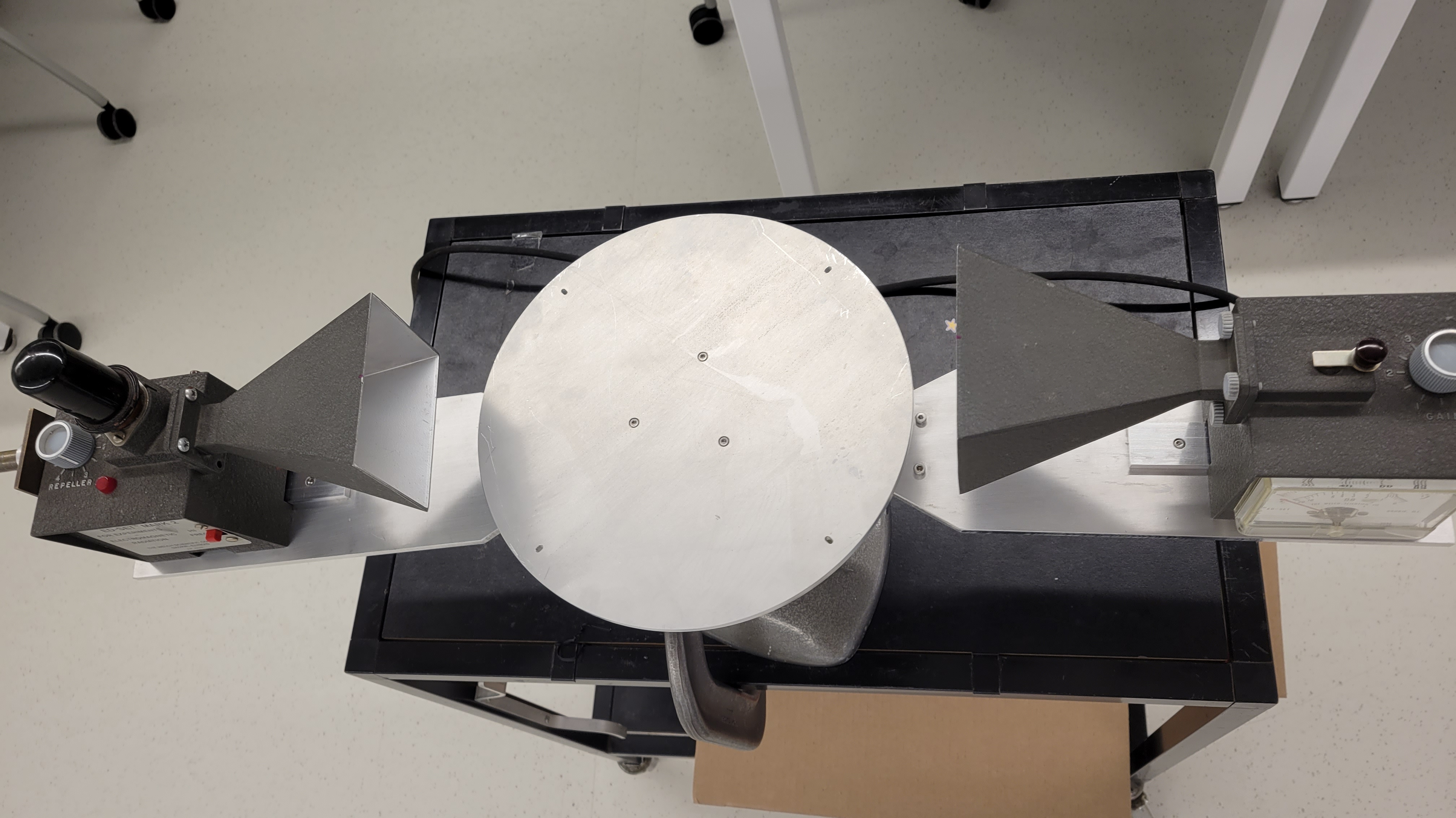
- A rotating table with two arms - one in fixed position for the transmitter and one rotating arm for the receiver. The table is also independently rotatable, with degree measurements
- 2 aluminum top and base blocks (215mm x 215 mm x ~20mm) for each different lattice structures
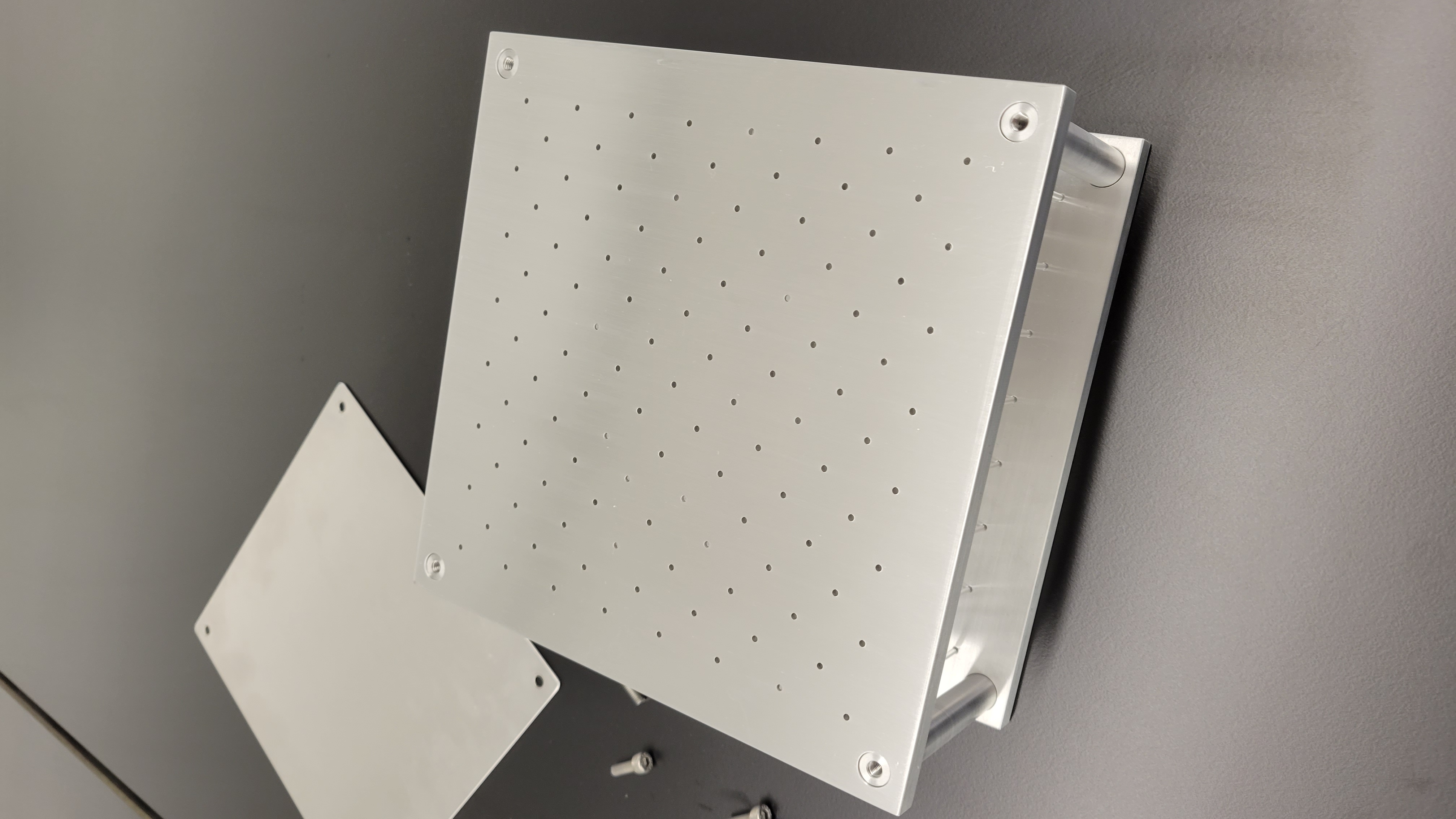
- ~200 plexiglass rods with dielectric constant of 3.5, 1.5mm OR 2mm diameter and 5-6 cm height
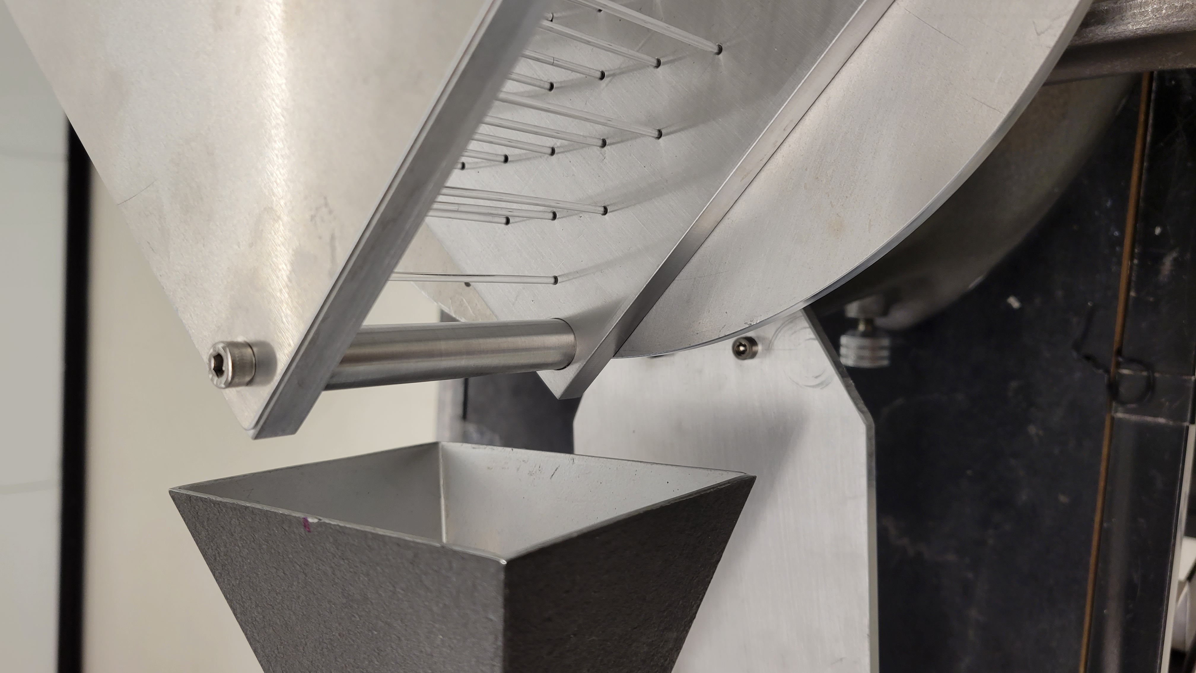
The lattice structure is made from 2 aluminum top and bottom square blocks of roughly 215mm x 215mm of appropriate thickness, with an aluminum rod (of similar height to the microwave transmitter and receiver's opening) at each corner for support. The bottom block is drilled half-way and the top block is drilled all the way through with the lattice arrangements, such that the plexiglass can be slided in as demonstrated below. The purpose of this design is for flexible rearrangement of the lattice structure.
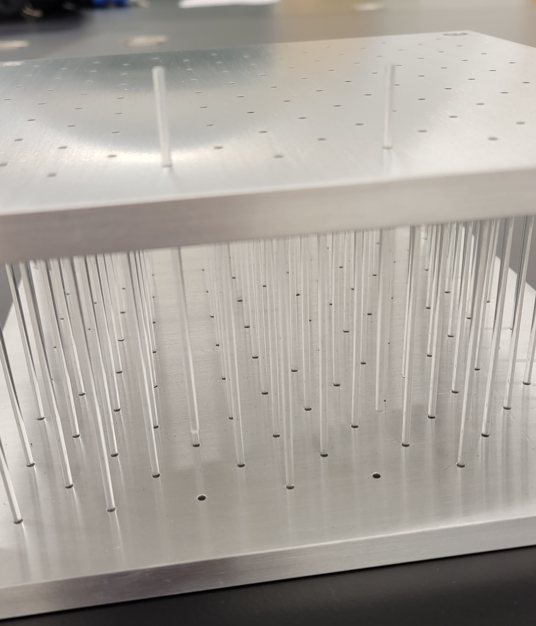
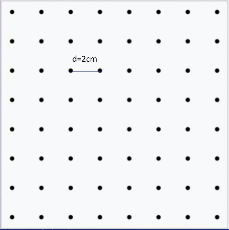
For the given microwave transmitter, a lattice spacing of 2cm was chosen. The first lattice structure is a 8x8 square lattice structure.
The next lattice structure is the same as above except with a center "atom" inside each square to represent a centered-square lattice structure. Note that due to the higher density, the received signal intensity will be higher for this second lattice structure.
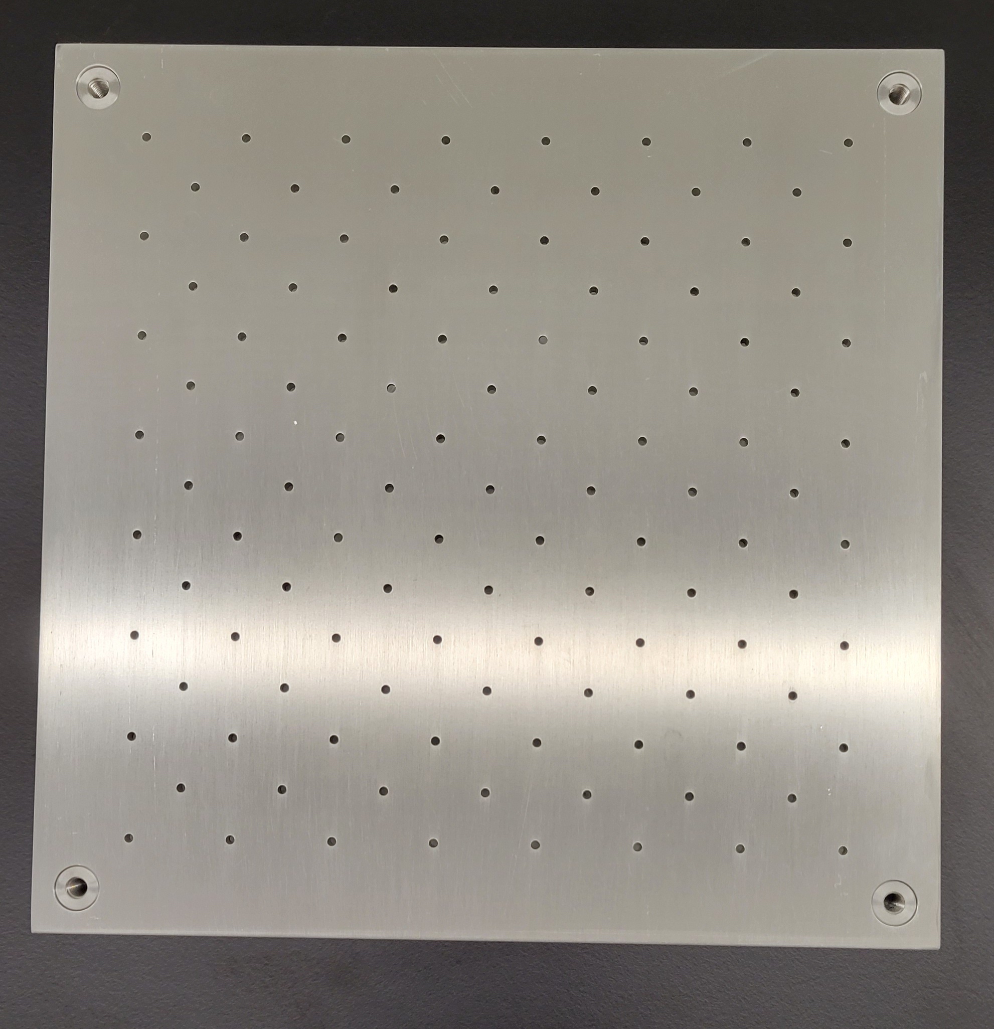
An aluminum sheet is then placed onto the top block and secured with screws at the four corners so that the plexiglass rod is secured in place.
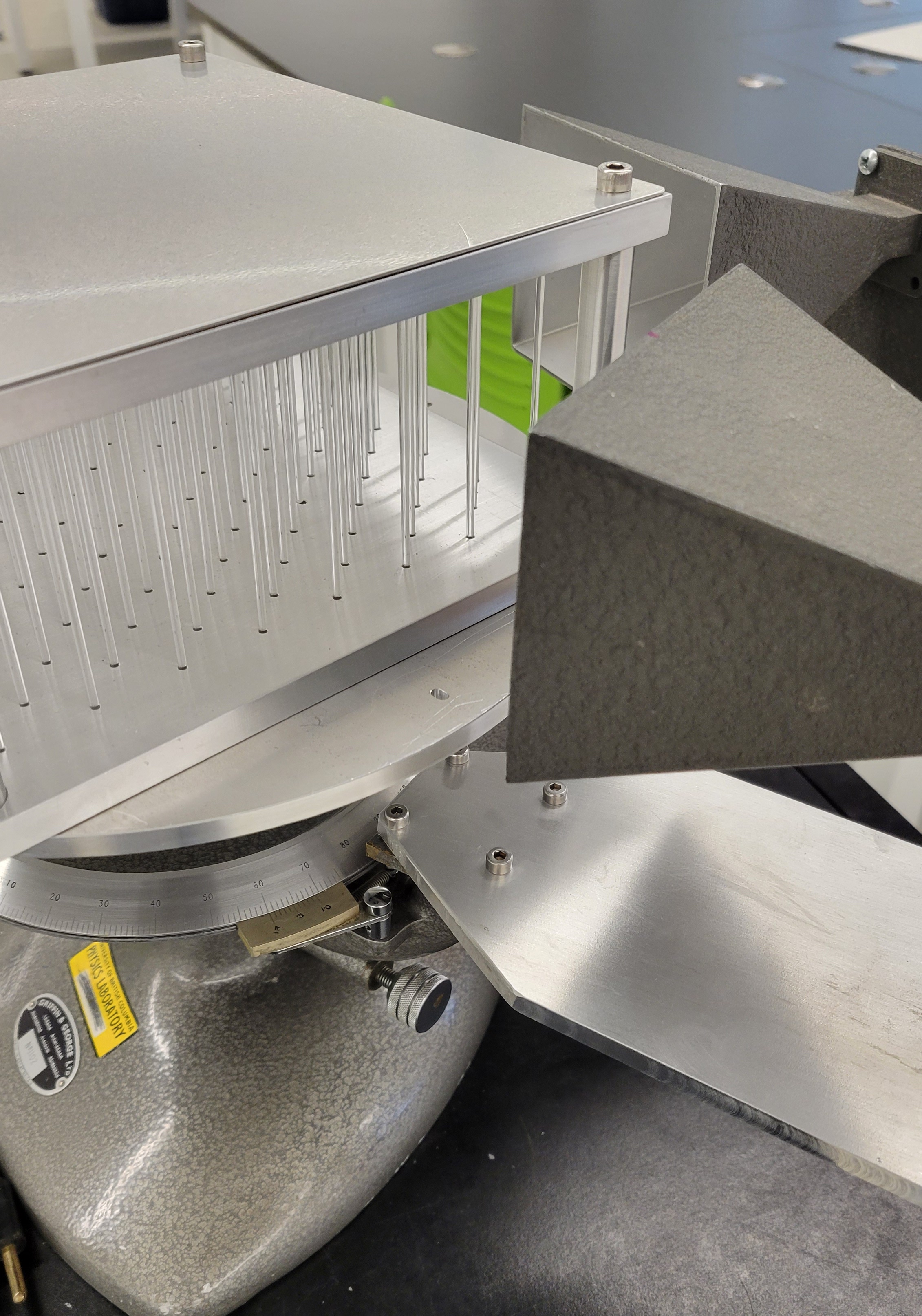
The arms and rotating plate's height were adjusted such that the transmitter and receiver openings are aligned with the height of the lattice structures.
1. Set up the rotating table such that the two arms are aligned. Place the transmitter on the fixed arm, and the receiver on the rotatable arm.
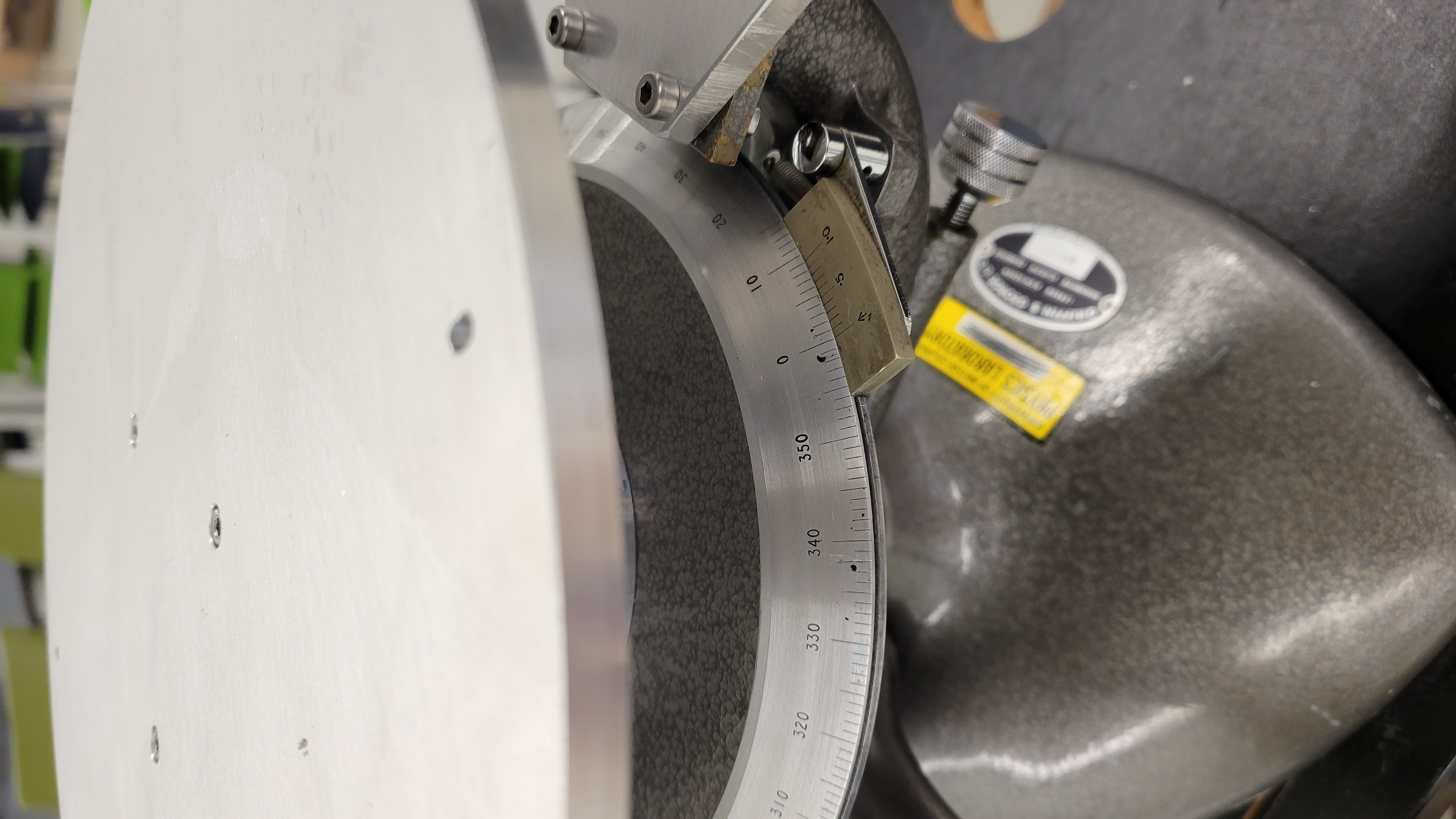
2. Rotate the center rotating plate such that the reading starts at 0 degree.
3. Place the lattice structure onto the center plate. Make sure the lattice grid line is also aligned (parallel/perpendicular) with the transmitter/receiver.
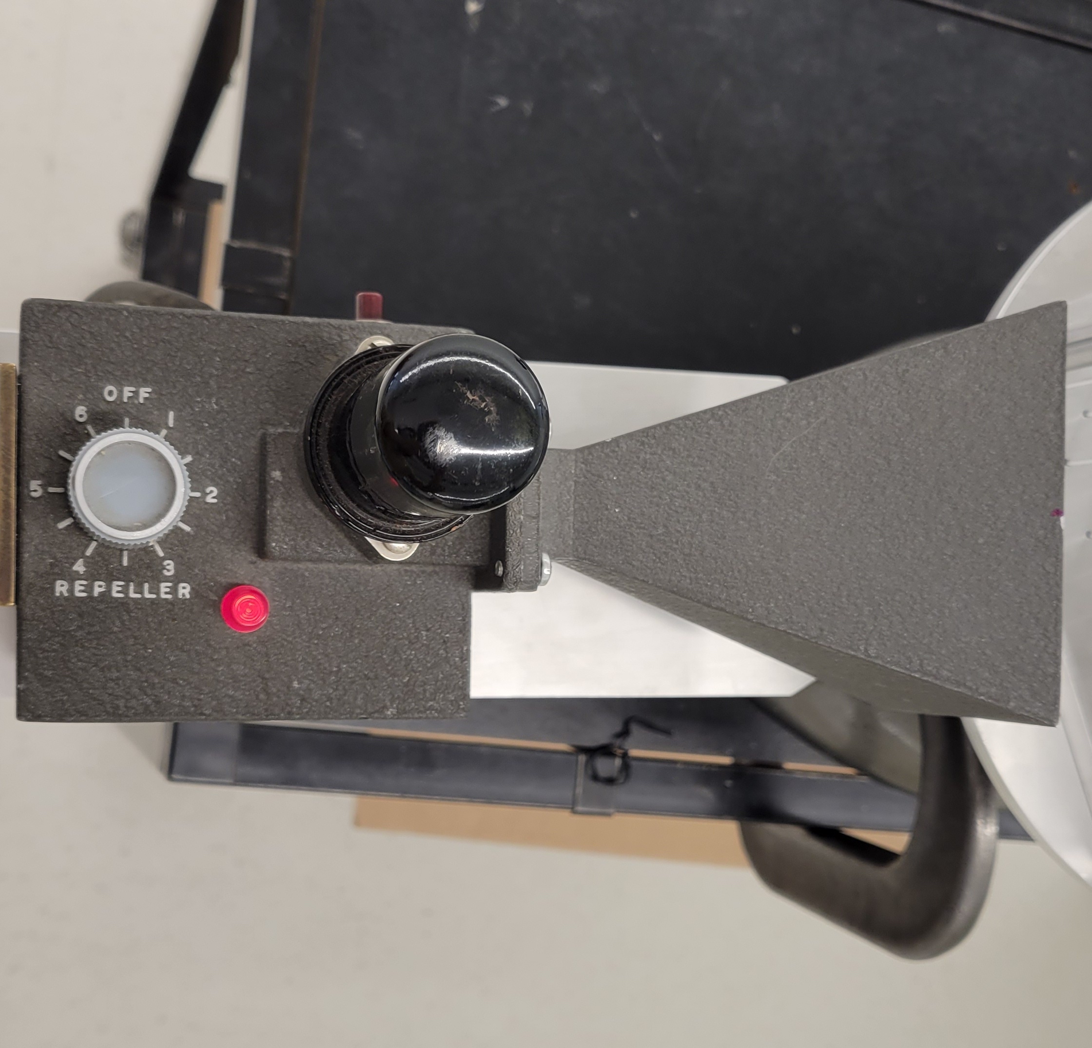
4. Turn on the transmitter. Adjust the settings for maximum received signal. For our setup, the repeller on transmitter is set to 3, and the gain on receiver is set to maximum (6).
5. Rotate the plate counter-clockwise by the intended angle. Example of a 60 degree counter clockwise rotation is given below.
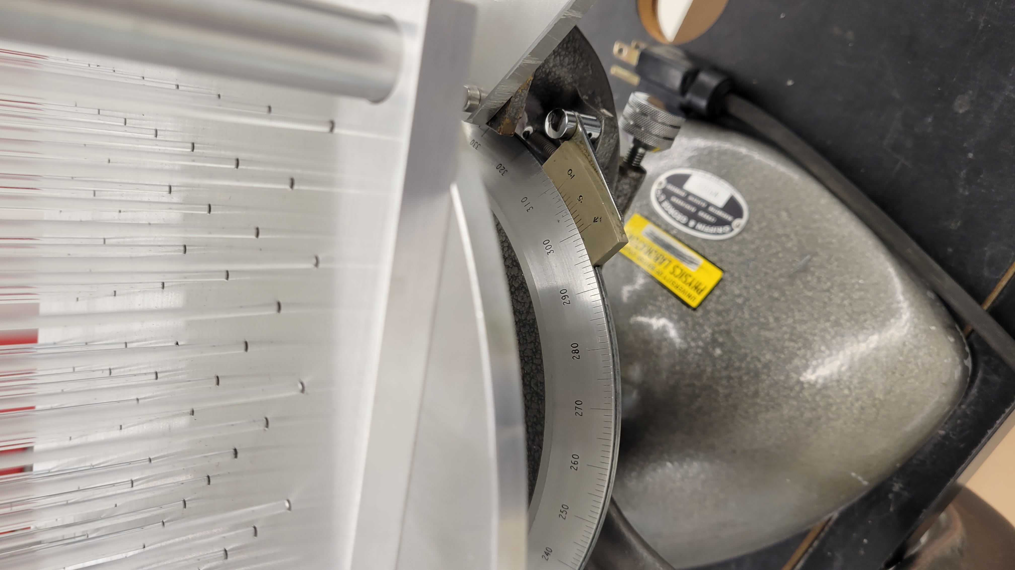
6. To read the reflected radiation, rotate the receiver arm by twice the intended angle, which returns the measurement reading back to the intended angle. Example of rotating the arm counter-clockwise by 120 degree from the above step, which returns measurement reading back to 60 degrees is given below.
7. Do multiple readings of angles around the angle of maxima to show the local maximum reflected radiation measurement. Make sure to adjust the rotating arm by twice the angle the lattice structure is adjusted.
8. Repeat with other lattice structures.