
The purpose of this demonstration is to teach students about the application of physics in electronics through the construction of a flex sensor glove. This glove is constructed using flex sensors to track finger movement and a gyroscope to detect hand rotation. The main focuses will be on learning about how to use these sensors with a microcontroller and interpreting their outputs to move a virtual hand, created in a software called Unity.
The intended audience is for a high school electronics or robotics class, who have some basic knowledge on circuits and Arduino’s (microcontroller). However, this can also be shown to a high school physics class to introduce them to electronics.
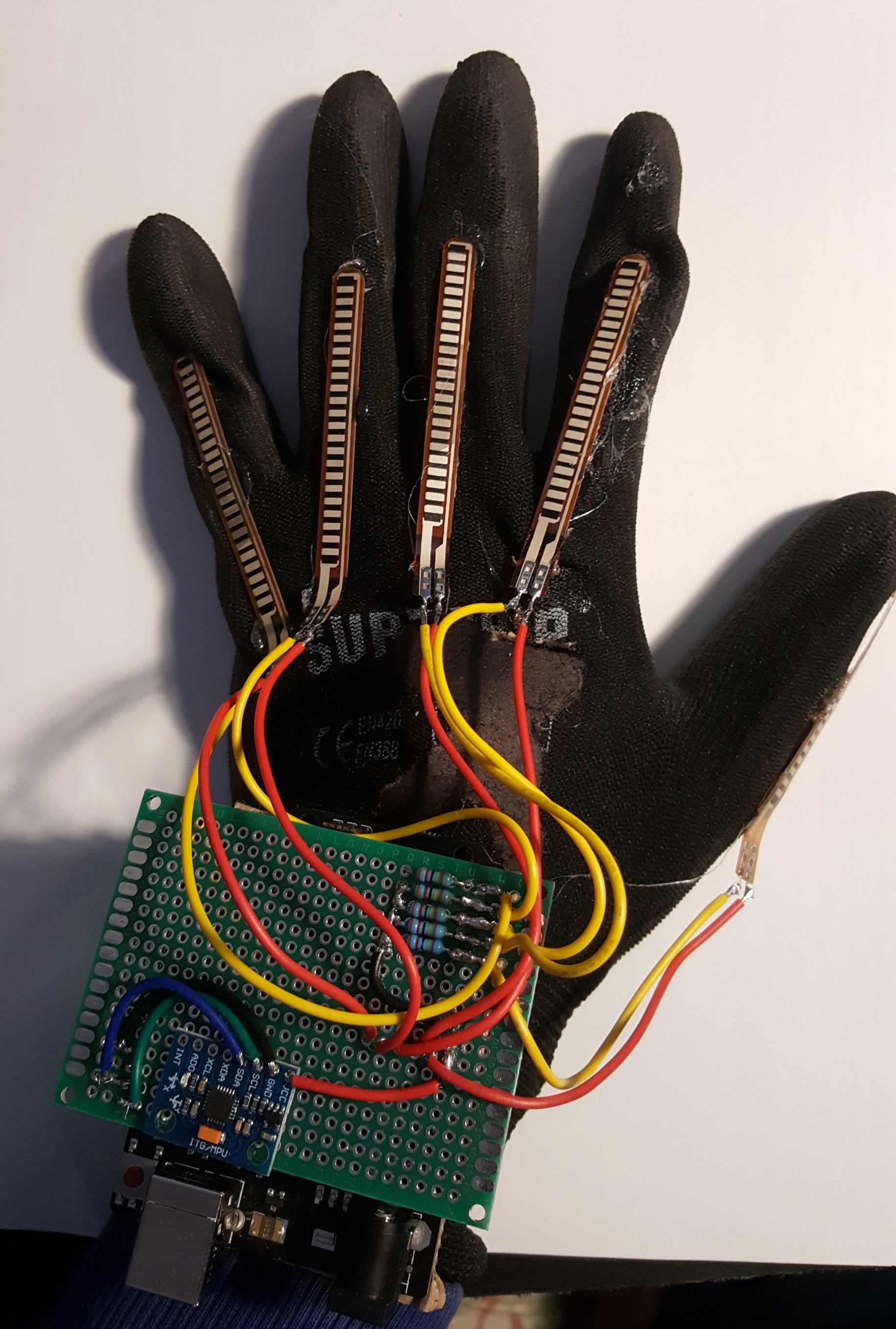
The flex sensor glove is a glove that uses a flex sensor attached above each finger to track the bending of the finger and a gyroscope on top of the hand to track rotation. These sensors are read by a microcontroller (Arduino) and then passed onto Unity via serial communication. Unity handles animating and rendering the virtual hand and its interactions with the virtual reality. The exact materials used are listed at the bottom of the page under Resources.

I used a nitrile glove, with the flex sensors hot glued on top. The gyroscope was attached to a perfboard where all the circuitry was soldered onto. The perfboard is then attached to the microcontroller using male header pins.

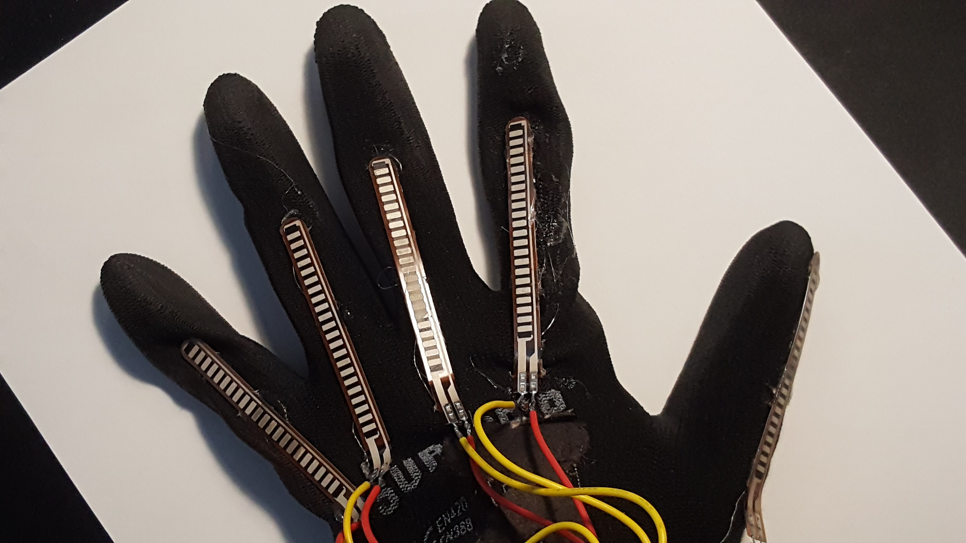
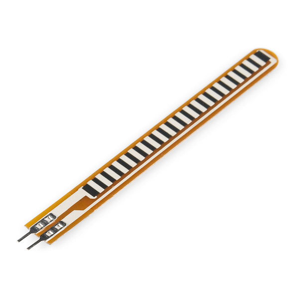
Flex sensors are a type of variable resistor whose resistance increases as they are bent. For this project I used a 26 kΩ, 2.2" flex sensor.

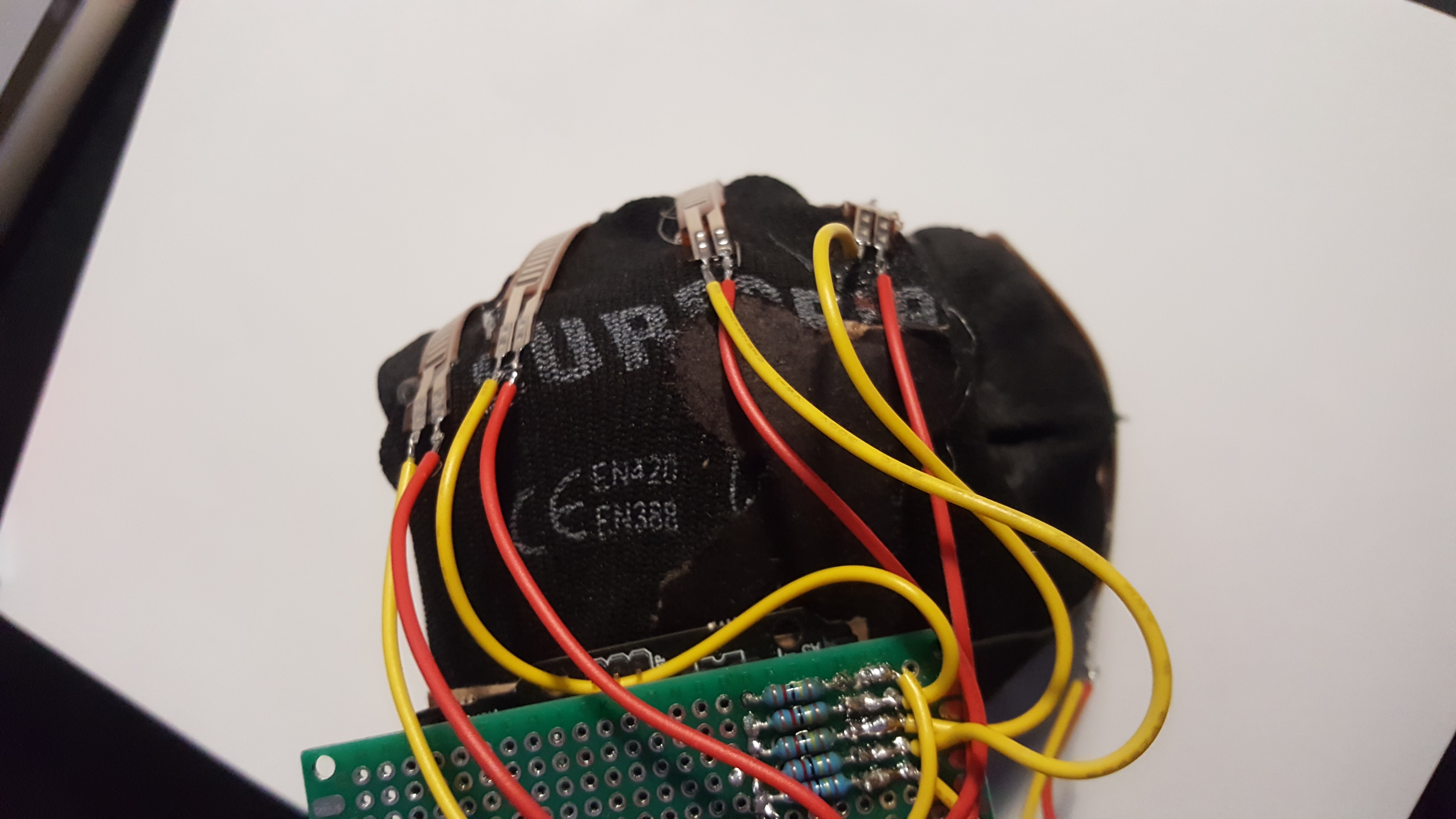
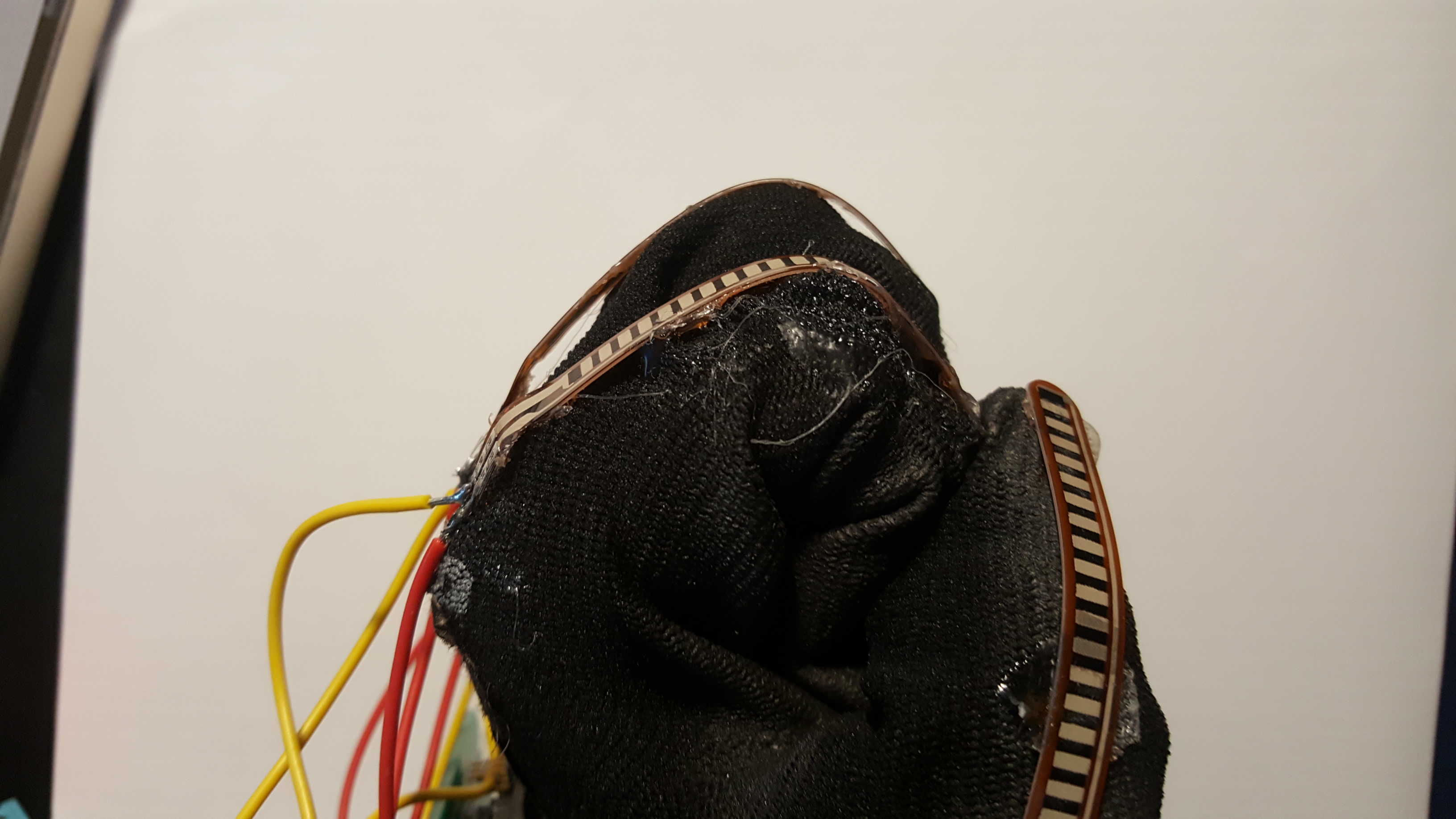
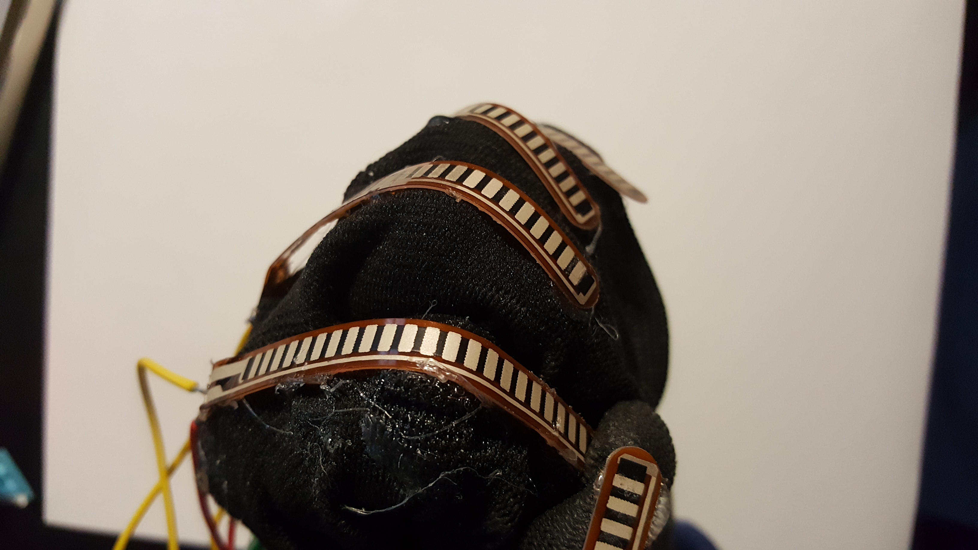
A picture of the glove when forming a fist.
I am using a MPU-6050 accelerometer and gyroscope. For this project I am only using the gyroscope, but the code and schematic provided allows for use of the accelerometer as well.


The Arduino is responsible for reading the outputs of the flex sensors and converting these to the angle that the finger is bent, and reading the outputs of the gyroscope sensor. The Arduino then sends this information through serial communication.
Each iteration of the loop() will read the output voltage from each of the 5 flex sensors, and will return the angle bent as the following serial output:
Left:Index:11.00
The deliminaters in the string are the ":".The first element corresponds to which hand we are reading from ("Left" in this case"). Note we are only using 1 flex sensor glove for this project, but the code has been written for the use of 2 flex sensor gloves if one wishes; with minimal changes required.
The second element corresponds to which part of the hand we are reading from ("Index" in this case refers to the index finger, Another example would be "RotateX" - which corresponds to the rotation about the x-axis). The third element corresponds to the respective value of the previous element. If the previous value was the index finger, this value would be the angle that that finger was bent.
If the second element was "RotateX" then this would be the angle that the hand was rotated about the x-axis (in degrees). In this case we have the value "11.0", which all together corresponds to a bending angle of 11 degrees of the left index finger.
The input pins for the flex sensors are set to be from A0-A4 as seen below:
If you would like to change the pins used, these constants can be changed and are found inlines 11-14.
                           // input pins from the flex sensors

                           const int THUMB_PIN = A0;

                           const int INDEX_PIN = A2;

                           const int MIDDLE_PIN = A1;

                           const int RING_PIN = A3;

                           const int PINKY_PIN = A4;
The resistance of the flex sensor and R2 in the voltage divider are entered on lines 18-20:
These 3 constants should be changed to the corresponding resistances used, if your flex sensor and/or R2 resistor used are different.
                           const float R_DIV = 14000; // Measured resistance of R2 in Ohms

                           const float NOMINAL_RES = 26000; // resistance when straight

                           const float BENT_RES = 60000.0; // resistance at 90 deg
Unity is responsible for rendering and animating the virtual model of the hand. Creating the virtual simulation in Unity was quite an involved process and this documentation page is not meant to be a tutorial on Unity. Thankfully all the work in Unity has been done for you! I have listed many of the helpful resources I had used under the resources section for the reader to get started with if this is something they wish to modify or change.
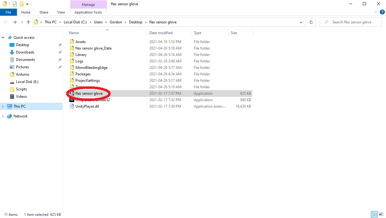
To use this simulation, unzip the contents of the file and set the the correct serial port for the microcontroller that you are using. This can be done by navigating to the grab.cs file under flex sensor glove\Assets\ and changing line 31:
private string COM_PORT = "COM6";
Here my arduino is on COM6, this value should be changed to the corresponding port of your microcontroller. Afterwards save the file. Next run flex sensor glove.exe.
Note that this project requires Unity version 2019.4.21f1 Personal and Windows operating system to work.


Datasheet
Hookup Guide
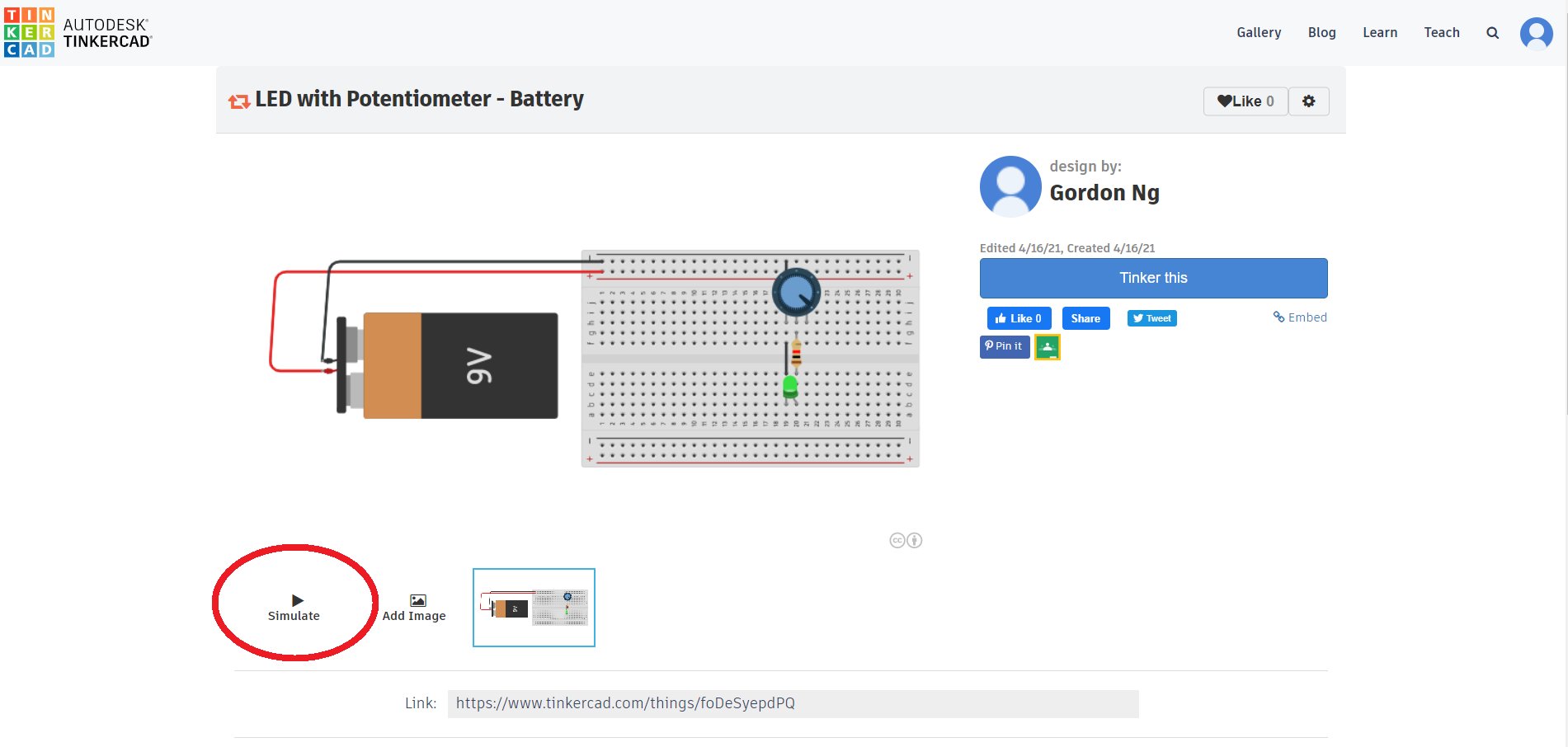
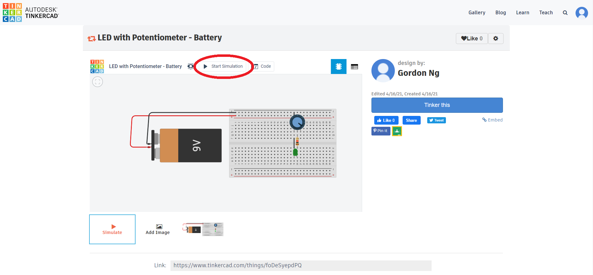
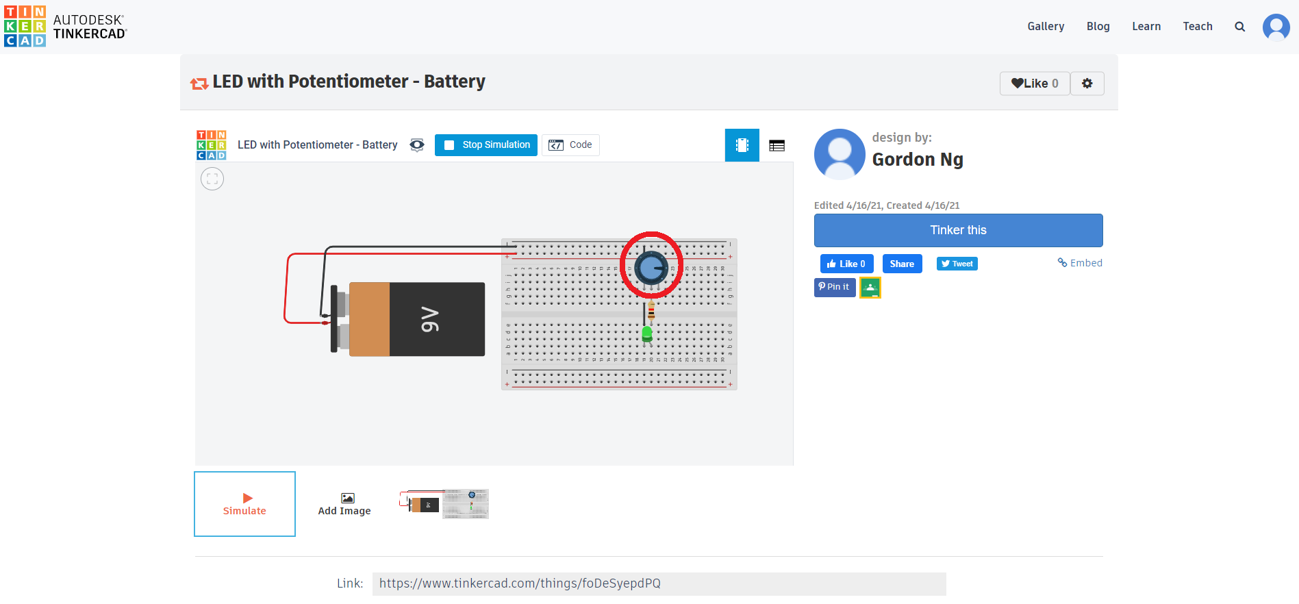
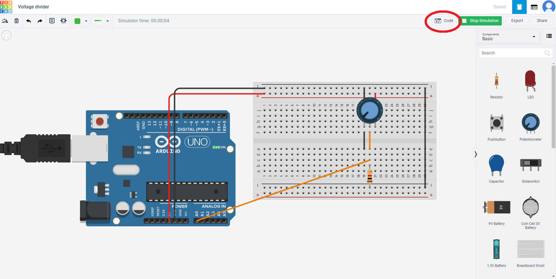
Voltage Divider
Example on reading voltage from potentiometer
Tutorials