Visualizing Wifi - Tiger zuo
Introduction
My interest in this project is inspired by thinking of how to see through walls and objects. Walls are not transparent like glass but they are penetrable by radio waves of many frequencies, and perhaps through building a device to visualize wifi, one can determine objects and shapes in another room. This turned out to be an interesting idea and I think there is a lot to be taught to students through the visualization of radio waves.
The major topic I want to discuss with this project is the connection of light and electromagnetic waves in general. Visible light seems to have a disconnection to EM waves in general due to the fact that we can observe them. When I think of the absorption and emission of photons, I think in terms of visible light, but photos really don't have to be visible light at all. Visible light is just a specific range of frequency that we can observe. By making the connection between light and wifi, I hope it would give students a better understanding of EM waves in general.
Design
Version 2
I know I needed to make a directional antenna to detect and isolate the signal. I made two version of the antenna, my main refereces for the first one was an online calculator. For the second version this blog was really helpful. The reason I made two version is that the first one made of cardboard was not very sensitive to direction changes for some reason, also I wanted to build a more sturdy one.
The below will be a copy of the blog's text for reference
Parts Used To Build This Antenna:
———————————————————
Brass Sheet Metal 0.016″ X 6″ X 12″ Qty: 1
Need To Cut The Following Circles From The Piece Of Metal
90mm Circle Qty: 1
68mm Circle Qty: 1
54mm Circle Qty: 1
38mm Circle Qty: 1
37mm Circle Qty: 3
———————————————————
Each Circle Will Need To Have A Hole Drilled In The Middle Of The Circles. That Will Fit The All Thread Through. “Please Be Careful”
———————————————————-
You Will Need A Piece Of All Thread That Is 6 1/2 Inches Or 165mm Long “I Used A 5/16 Inch Or 8mm Dia”.
You Will Need Around 12 Nuts That Will Be Used For The All Thread.
The distance between the plates are labelled below in mm.
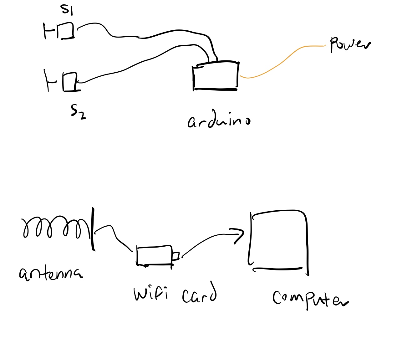
Then there needs to be the wifi card that attaches to the antenna, I used a regular usb antenna which I had laying around. I soldered the signal end of the antenna to the input sigal on the wifi card and then base plate to the base of the antenna.
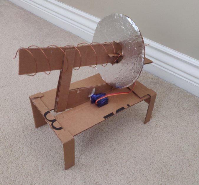
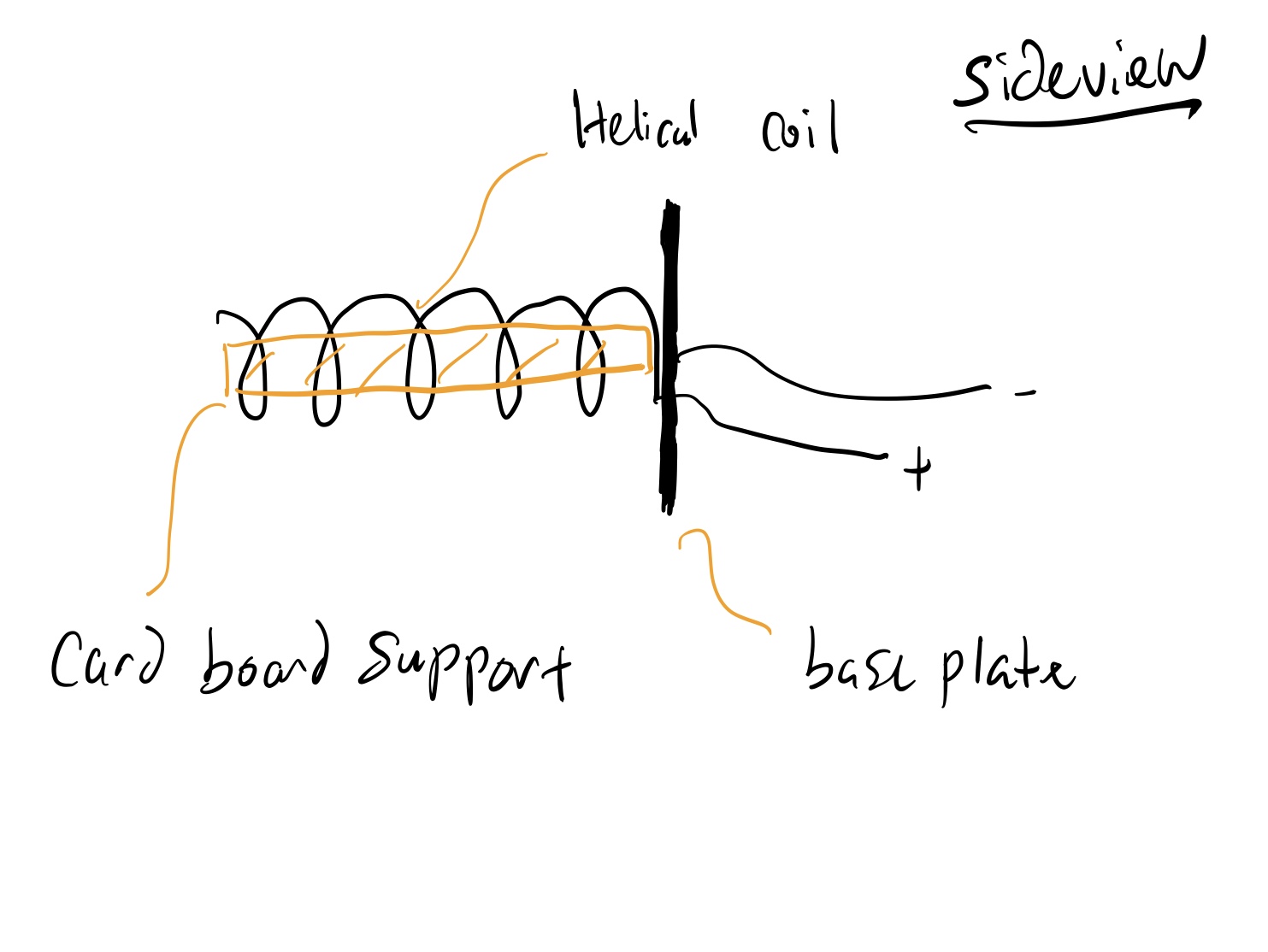
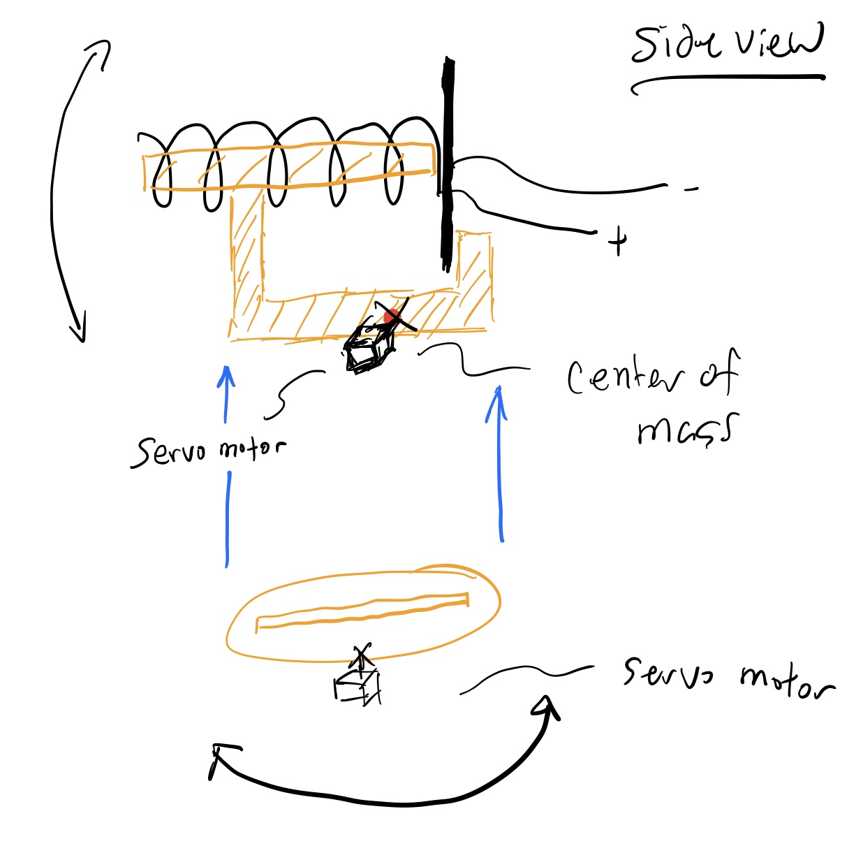
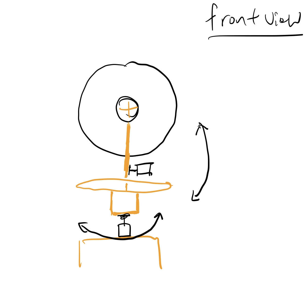
The above shown is my second version of this antenna, the first version is made of cardboard, aumium foil and copper wires. The wifi signal for this antenna was great initally and I found it to be unstable after a bit, the copper wires can bend sometimes and really small defects could have a big effect on the gain of the signal. The orginall design also consisted of a rotaion mount on servo motors but the mount was only made of cardboard and cannot hold up to the weight of the metal antenna. I tried to build a new mount for the metal antenna as well but just didn't have to tools for it. The way to make this project more interesting is to have the antenna mounted on a rotating mount that could spin around and then log the signal strength of each point in space. A 2D plot can then be made with the signal strength and (r,θ). That would be a really visually appealing way to present the project and that was my orginal intention.
Version 1
Software
I connected the usb wifi card to a ubuntu laptop running Linssid. You can install the software by typing:
sudo add-apt-repository ppa:wseverin/ppa
sudo apt-get update
sudo apt-get install linssid
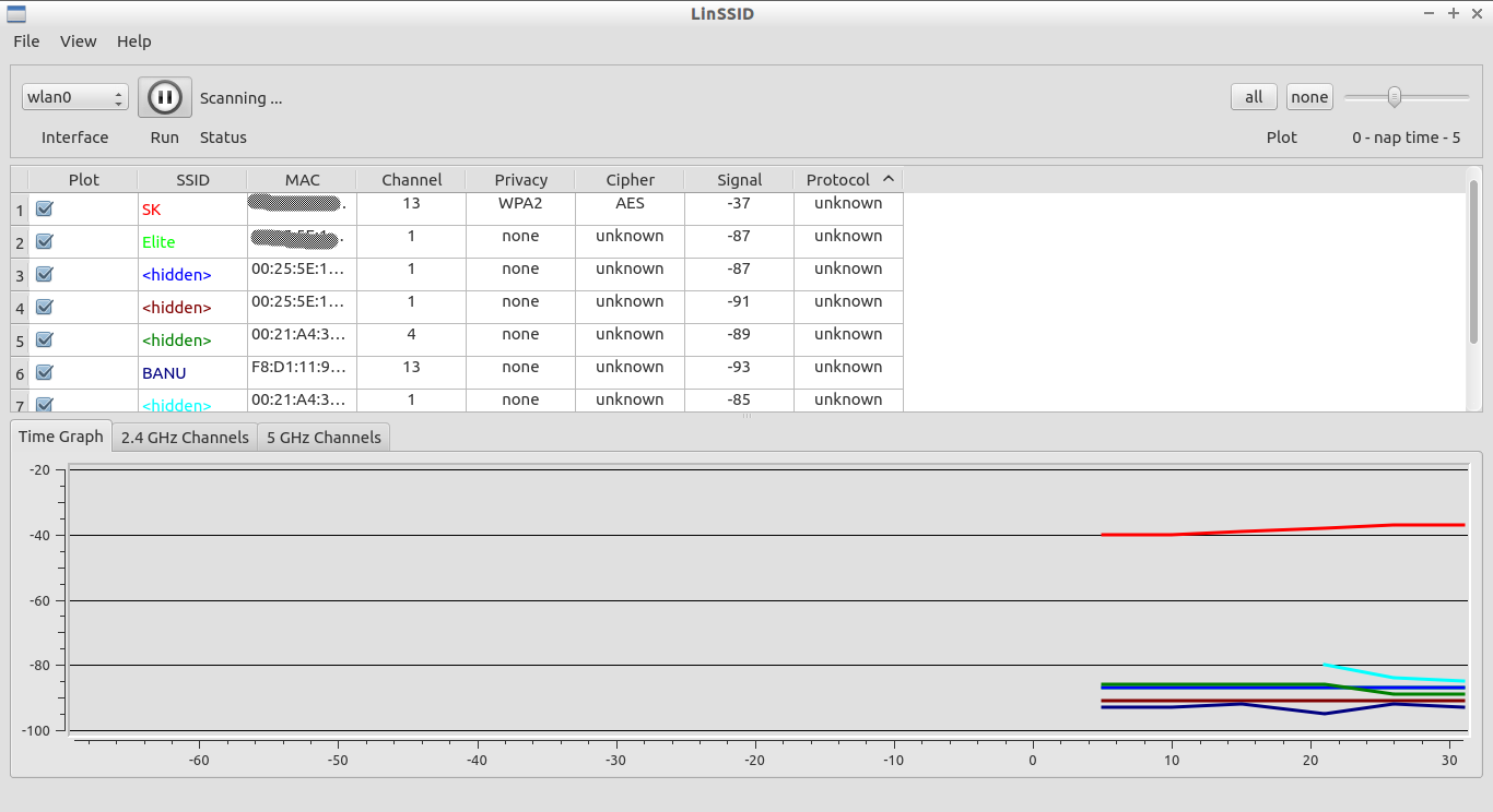
After the install you will see this
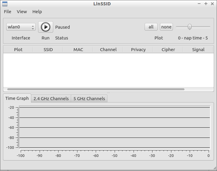
Then you can beginning scanning the network by pressing the play button and networks will show up, by orenting the antenna in different directions you can see different network with different strengths being plotted.
Presentaion
Here are the slides to my presentation.