Waves are an important topic taught is secondary school physics classes. What students learn from this subject can be applied not just to waves in nature, such as ocean waves and sound waves, but also to mathematics, engineering, and more complex physical theories. Waves can often be a 'dry' topic for some high school students, in which case I think it is important to be able to demonstrate the 'cool' physical properties and capabilities of them to inspire young minds. For some, the math itself is enough to excite a person, but for others, its what that math can accomplish and produce in our real world that brings them wonder.
One of the best ways to communicate how waves can interact with us in our daily lives is through sound. Many students, when they first think of waves, think of ocean waves. However, sound waves, being invisible to our naked eye, are something that many high school students might not realize have equal or more interesting properties. By investigating sound waves properties, we can also learn about how pressure works in air, and thus, can understand more about how things such as airplanes fly. By investigating waves, sound, and air pressure with a high school level class through demos like acoustic levitation, we can effectively and visually teach new, but simple, topics to students, while also inspiring them with the world of physics.
Theory Behind Waves
There are two types of forms physical waves come in. There are transverse waves, where the surface oscillates perpendicular to the direction of the waves travel, and longitudinal waves, which consist of patterns of alternating compressions and rarefactions travelling along the waves path. Transverse waves have several notable characteristics. Their amplitude (A) which is the height of their highest point. The wavelength (λ), which is the distance it takes for the waves pattern to repeat, and is often best measured from peak to peak or trough to trough. A wave's frequency (υ) is the most complicated of the transverse wave's characteristics to measure. It is defined as number of waves that have passed a specific point in an amount of time, often measured in Hertz (Hz), which is the number of waves passed per second. They can be more easily measured by finding the waves period (T), which is the amount of time it takes one wavelength to fully traverse a point. The inverse of the period gives the frequency.
υ = 1⁄T
Another way to measure the frequency is to take the speed the wave is travelling at (v) and divide by it's wavelength of the wave.
υ = v⁄λ
When two waves come across each other in the same location, they go through something called interference. At interference, the amplitudes of the waves at each point sum together to create either constructive interference where the net amplitude is greater than the individual ones, or destructive interference where the net amplitude is less that the individual ones. If the waves are travelling in opposite directions, once they pass each other they will regain their individual amplitudes and waves speeds, as neither of the waves energy is lost.
If consecutive wave patterns cross paths, the total interference can be a combination of constructive and destructive interference, if the frequencies or waves speed is different. This interference can create wave patterns that look strange, and do not look like conventional sinusoidal waves. By changing the frequency, amplitude, wavelength, or wave speed of any of the subsequent waves, the net wave pattern can change drastically.
A particularly interesting physical phenomenon, resulting from interference, is generated from two waves, equal in wave speed and frequency, moving in opposite directions, with their x-intercepts matching in location. This creates a standing wave, which is a wave that oscillates vertically, but not horizontally. Standing waves have two important positions, they have nodes, which are locations that do not oscillate vertically at all, and anti-nodes, which are positions on the waves that have the maximum oscillation. The distance between nodes is half a wavelength of the subsequent waves. Typically, standing waves can be seen in the physical world in the form of resonance frequencies, when waves are reflected off a surface at a point where the waves amplitude is zero.
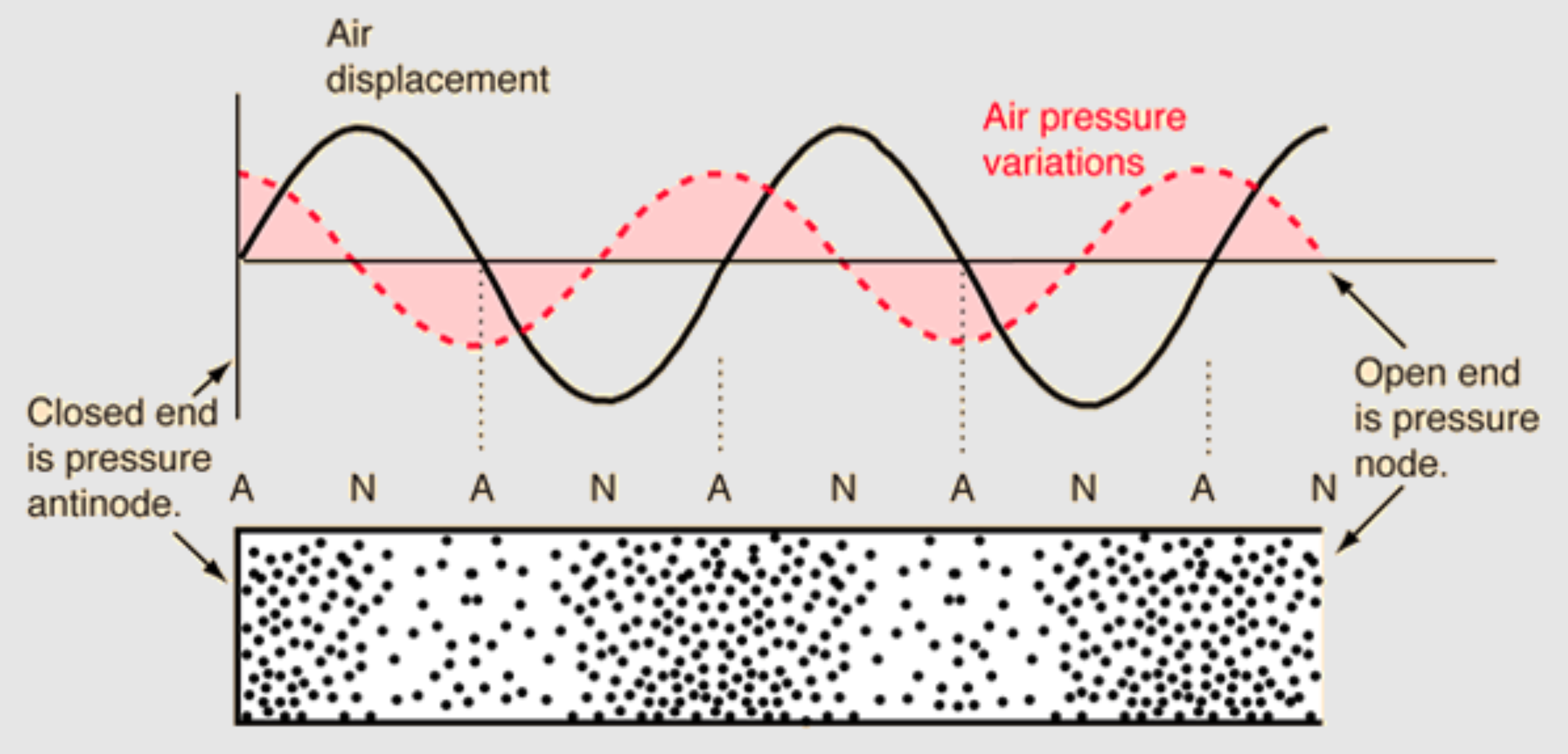
Standing waves are not just a transverse wave phenomenon, they also exist in longitudinal waves, the same waves that travel in air and through slinkies. If we compare a transverse standing wave and a longitudinal standing wave in air, as seen in figure below, pressure nodes are created, where the pressure does not oscillate.
Objects in mediums tend to prefer being in areas of low air pressure. This same physical phenomenom is how air planes fly in the air, using Bernoulli's principle, where fast moving air create areas of lower air pressure.
In pressure antinodes, the pressure oscillates rapidly from high to low. Light objects will tend towards volumes of low air pressure and stability, hence why light enough objects can be suspended in pressur nodes. If multiple standing waves are created with their nodes aligned at a single location, constructive interference occurs, increasing the amplitude (or pressure oscillations) in the wave, making it harder for an object to escape the pressure node.
Slides for 45 min Lesson
Instructions and Materials on How to Build an Acoustic Levitator
On this page we will go over all the steps needed to build an in-class acoustic levitator
Materials:
Ultrasonic Distance Sensor - HC-SR04 or Single 40 kHz Ultrasonic Transducer
Arduino Nano
12V Power Supply with 5.5x2.1mm Male Plug
Female Power Adapter DC Barrel to Screw Plug Jack Connector 2.1x5.5mm
Jumper Wires (Female to Female, Female to Male)
12AWG black and red wire
Popsicle Stick
Cardboard
Styrofoam
Tools
Wire Strippers
Tweezers
Screwdriver
Soldering Iron
Desoldering Pump
Desoldering Wick
USB 2.0 A Male To Mini B 5 Cable
Glue Gun
Exacto Knife
Ruler
Instructions:
The picture below shows the schematic of the circuitry required to power the ultrasonic transducers to produce 40 kHz pressure waves. On this page, we will go over each step to set up the circuitry and the transducers to create an acoustic levitator.
Step 1:
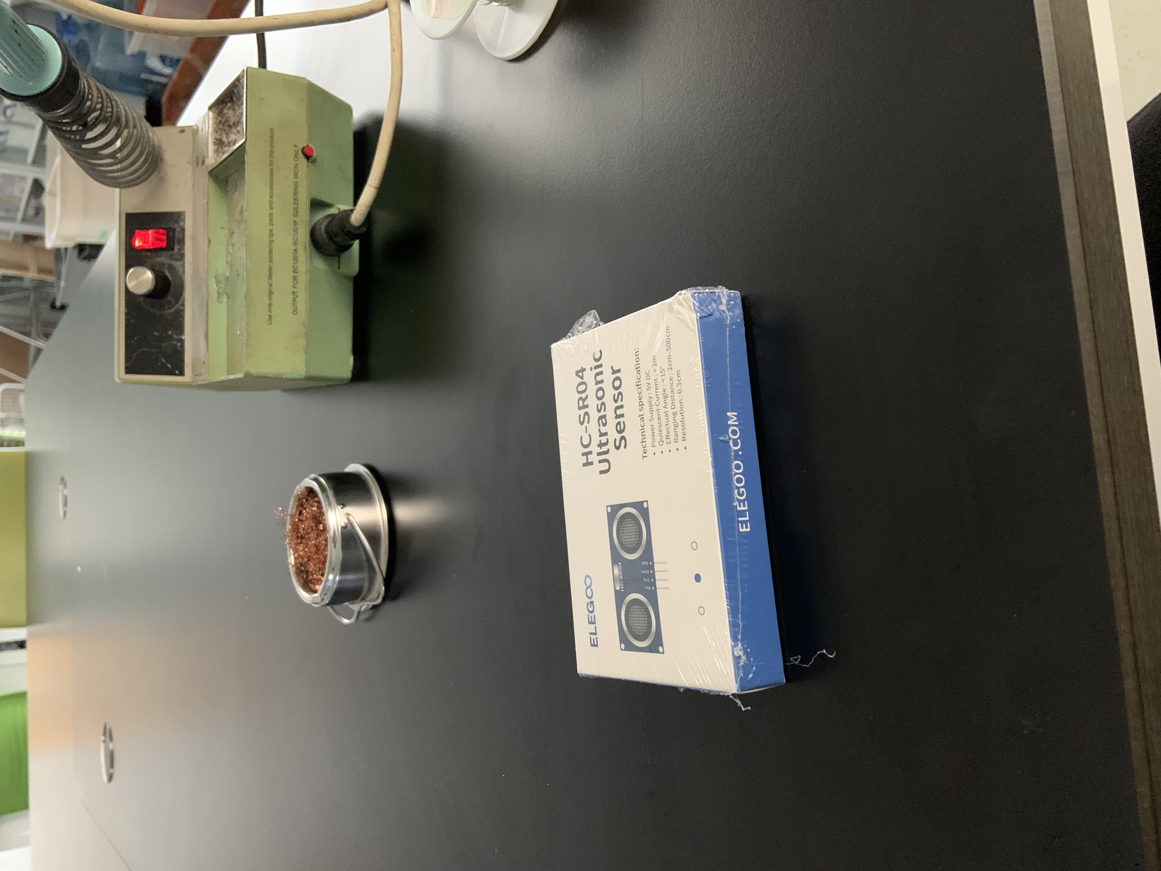
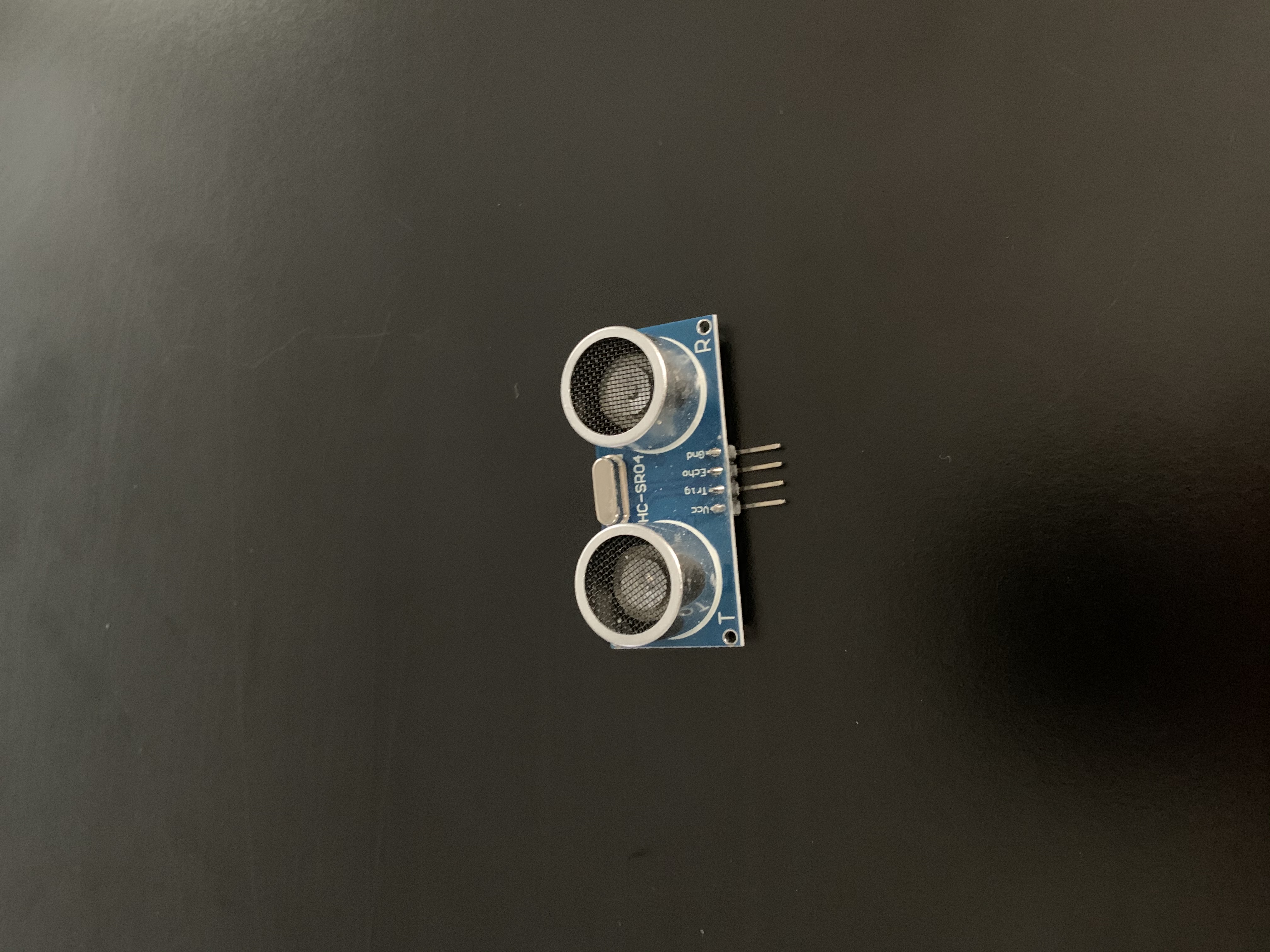
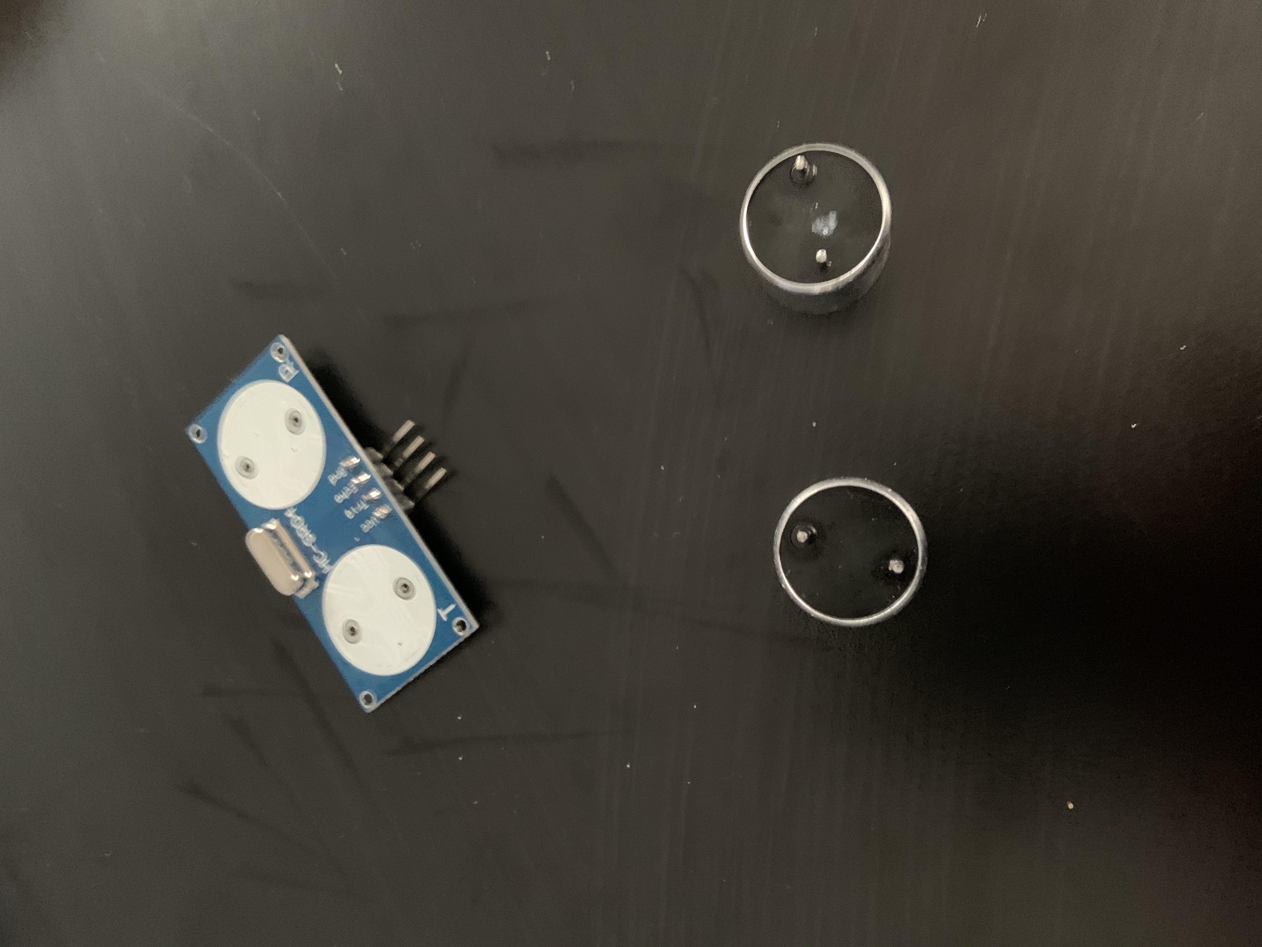
If you are using a 40 kHz Ultrasonic Transducer that was bought by itself, you can skip the next __ steps. If using the HC-SR04 Ultrasonic Distance Sensor, you will have to desolder the transducers from the PCB. Start by removing the sensor from its package and flipping it onto its back, revealing where the pins for the transduvcer are attached.
Turn on your soldering iron, then appliy it to each of the four pins one at a time. The pins can be seen in the image below circled in red. For each pin, hold the iron on it until the solder around the pin is liquified, then use the desoldering pump to suck out the the solder while it is still liquid. If some solder is still connecting the pin to the PCB, place some solderwick between the iron and the pin to collect some of the leftover solder.
Check out this YouTube video for a great tutorial on how to desolder!
Once you have removed enough solder, grab the transducers and pull them out from the PCB. This will involve some force, as the transducers are not likely to come free with ease.
Step 2:
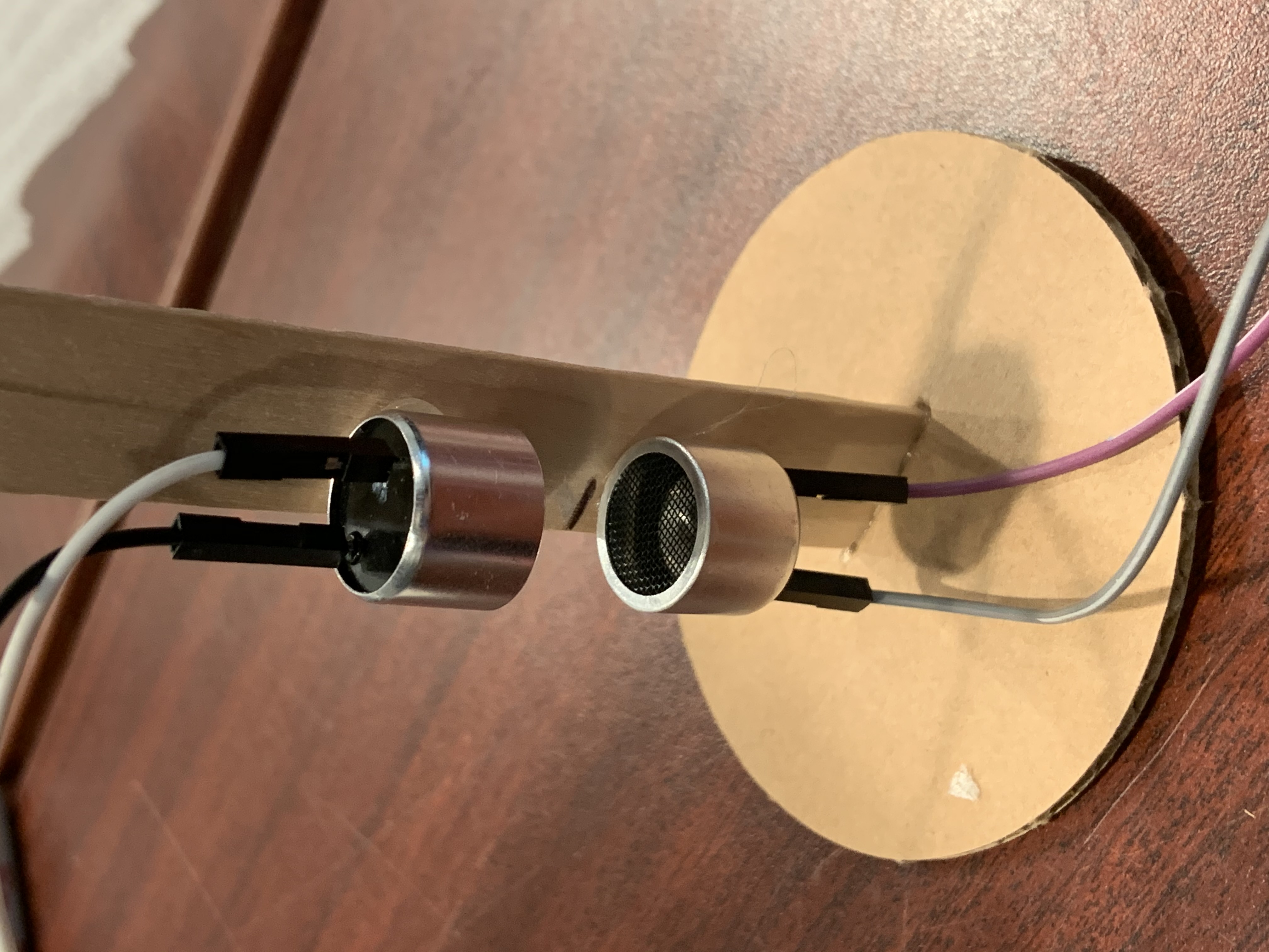
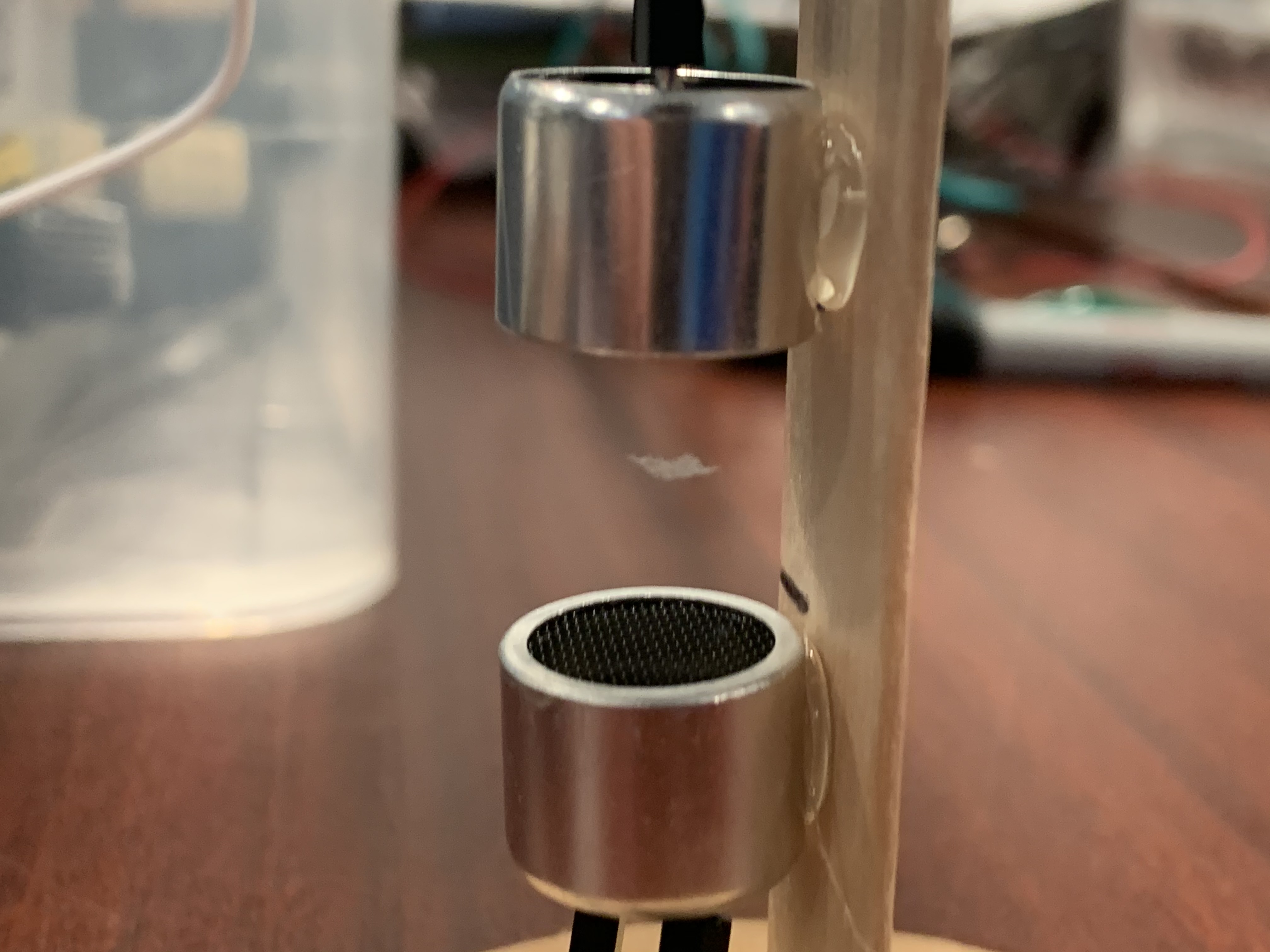
Using a ruler, draw two lines in the middle of the popsicle stick, 1.5 cm apart from each other. Use the hot glue gun to glue the two (recently desoldered) transducers to the popsicle stick so that they are facing each other and have their edges lined up with the lines you recently have drawn. Using a knife or scissors, cut one end of the popsicle stick off. This end will be used to plant your experiment into a cardboard base. With the cardboard, cut a square are circular shape, large enough to hold the popsicle stick. Then cut a small slit in the middle of the cardboard, careful to only punctur one surface of the cardboard, and not cut all the way through it. The slit should be a little larger than the width of the popsicle stick. Fill the slit with glue from the glue gun, then place the cut end of the popsicle into the slit.
Step 3:
Connect the Arduino Nano to your computer through the USB 2.0 A Male To Mini B 5 Cable. You will need Arduino IDE for this next step. Download this Arduino Code
to your computer, or copy it from below.
#include <avr/sleep.h>
#include <avr/power.h>

#define N_PORTS 1
#define N_DIVS 24

#define WAIT_LOT(a) __asm__ __volatile__ ("nop"); __asm__ __volatile__ ("nop"); __asm__ __volatile__ ("nop");  __asm__ __volatile__ ("nop"); __asm__ __volatile__ ("nop");__asm__ __volatile__ ("nop"); __asm__ __volatile__ ("nop");__asm__ __volatile__ ("nop"); __asm__ __volatile__ ("nop");  __asm__ __volatile__ ("nop"); __asm__ __volatile__ ("nop");__asm__ __volatile__ ("nop");  __asm__ __volatile__ ("nop");  __asm__ __volatile__ ("nop")
#define WAIT_MID(a) __asm__ __volatile__ ("nop"); __asm__ __volatile__ ("nop"); __asm__ __volatile__ ("nop");  __asm__ __volatile__ ("nop"); __asm__ __volatile__ ("nop");__asm__ __volatile__ ("nop"); __asm__ __volatile__ ("nop");__asm__ __volatile__ ("nop"); __asm__ __volatile__ ("nop"); __asm__ __volatile__ ("nop"); __asm__ __volatile__ ("nop"); __asm__ __volatile__ ("nop"); __asm__ __volatile__ ("nop")
#define WAIT_LIT(a) __asm__ __volatile__ ("nop"); __asm__ __volatile__ ("nop"); __asm__ __volatile__ ("nop");  __asm__ __volatile__ ("nop"); __asm__ __volatile__ ("nop");  __asm__ __volatile__ ("nop");  __asm__ __volatile__ ("nop");  __asm__ __volatile__ ("nop");  __asm__ __volatile__ ("nop")


#define OUTPUT_WAVE(pointer, d)  PORTC = pointer[d*N_PORTS + 0]

#define N_BUTTONS 6
//half a second
#define STEP_SIZE 1
#define BUTTON_SENS 2500
#define N_FRAMES 24

static byte frame = 0;
static byte animation[N_FRAMES][N_DIVS] =
{{0x5,0x5,0x5,0x5,0x5,0x5,0x5,0x5,0x5,0x5,0x5,0x5,0xa,0xa,0xa,0xa,0xa,0xa,0xa,0xa,0xa,0xa,0xa,0xa},
{0x9,0x5,0x5,0x5,0x5,0x5,0x5,0x5,0x5,0x5,0x5,0x5,0x6,0xa,0xa,0xa,0xa,0xa,0xa,0xa,0xa,0xa,0xa,0xa},
{0x9,0x9,0x5,0x5,0x5,0x5,0x5,0x5,0x5,0x5,0x5,0x5,0x6,0x6,0xa,0xa,0xa,0xa,0xa,0xa,0xa,0xa,0xa,0xa},
{0x9,0x9,0x9,0x5,0x5,0x5,0x5,0x5,0x5,0x5,0x5,0x5,0x6,0x6,0x6,0xa,0xa,0xa,0xa,0xa,0xa,0xa,0xa,0xa},
{0x9,0x9,0x9,0x9,0x5,0x5,0x5,0x5,0x5,0x5,0x5,0x5,0x6,0x6,0x6,0x6,0xa,0xa,0xa,0xa,0xa,0xa,0xa,0xa},
{0x9,0x9,0x9,0x9,0x9,0x5,0x5,0x5,0x5,0x5,0x5,0x5,0x6,0x6,0x6,0x6,0x6,0xa,0xa,0xa,0xa,0xa,0xa,0xa},
{0x9,0x9,0x9,0x9,0x9,0x9,0x5,0x5,0x5,0x5,0x5,0x5,0x6,0x6,0x6,0x6,0x6,0x6,0xa,0xa,0xa,0xa,0xa,0xa},
{0x9,0x9,0x9,0x9,0x9,0x9,0x9,0x5,0x5,0x5,0x5,0x5,0x6,0x6,0x6,0x6,0x6,0x6,0x6,0xa,0xa,0xa,0xa,0xa},
{0x9,0x9,0x9,0x9,0x9,0x9,0x9,0x9,0x5,0x5,0x5,0x5,0x6,0x6,0x6,0x6,0x6,0x6,0x6,0x6,0xa,0xa,0xa,0xa},
{0x9,0x9,0x9,0x9,0x9,0x9,0x9,0x9,0x9,0x5,0x5,0x5,0x6,0x6,0x6,0x6,0x6,0x6,0x6,0x6,0x6,0xa,0xa,0xa},
{0x9,0x9,0x9,0x9,0x9,0x9,0x9,0x9,0x9,0x9,0x5,0x5,0x6,0x6,0x6,0x6,0x6,0x6,0x6,0x6,0x6,0x6,0xa,0xa},
{0x9,0x9,0x9,0x9,0x9,0x9,0x9,0x9,0x9,0x9,0x9,0x5,0x6,0x6,0x6,0x6,0x6,0x6,0x6,0x6,0x6,0x6,0x6,0xa},
{0x9,0x9,0x9,0x9,0x9,0x9,0x9,0x9,0x9,0x9,0x9,0x9,0x6,0x6,0x6,0x6,0x6,0x6,0x6,0x6,0x6,0x6,0x6,0x6},
{0x5,0x9,0x9,0x9,0x9,0x9,0x9,0x9,0x9,0x9,0x9,0x9,0xa,0x6,0x6,0x6,0x6,0x6,0x6,0x6,0x6,0x6,0x6,0x6},
{0x5,0x5,0x9,0x9,0x9,0x9,0x9,0x9,0x9,0x9,0x9,0x9,0xa,0xa,0x6,0x6,0x6,0x6,0x6,0x6,0x6,0x6,0x6,0x6},
{0x5,0x5,0x5,0x9,0x9,0x9,0x9,0x9,0x9,0x9,0x9,0x9,0xa,0xa,0xa,0x6,0x6,0x6,0x6,0x6,0x6,0x6,0x6,0x6},
{0x5,0x5,0x5,0x5,0x9,0x9,0x9,0x9,0x9,0x9,0x9,0x9,0xa,0xa,0xa,0xa,0x6,0x6,0x6,0x6,0x6,0x6,0x6,0x6},
{0x5,0x5,0x5,0x5,0x5,0x9,0x9,0x9,0x9,0x9,0x9,0x9,0xa,0xa,0xa,0xa,0xa,0x6,0x6,0x6,0x6,0x6,0x6,0x6},
{0x5,0x5,0x5,0x5,0x5,0x5,0x9,0x9,0x9,0x9,0x9,0x9,0xa,0xa,0xa,0xa,0xa,0xa,0x6,0x6,0x6,0x6,0x6,0x6},
{0x5,0x5,0x5,0x5,0x5,0x5,0x5,0x9,0x9,0x9,0x9,0x9,0xa,0xa,0xa,0xa,0xa,0xa,0xa,0x6,0x6,0x6,0x6,0x6},
{0x5,0x5,0x5,0x5,0x5,0x5,0x5,0x5,0x9,0x9,0x9,0x9,0xa,0xa,0xa,0xa,0xa,0xa,0xa,0xa,0x6,0x6,0x6,0x6},
{0x5,0x5,0x5,0x5,0x5,0x5,0x5,0x5,0x5,0x9,0x9,0x9,0xa,0xa,0xa,0xa,0xa,0xa,0xa,0xa,0xa,0x6,0x6,0x6},
{0x5,0x5,0x5,0x5,0x5,0x5,0x5,0x5,0x5,0x5,0x9,0x9,0xa,0xa,0xa,0xa,0xa,0xa,0xa,0xa,0xa,0xa,0x6,0x6},
{0x5,0x5,0x5,0x5,0x5,0x5,0x5,0x5,0x5,0x5,0x5,0x9,0xa,0xa,0xa,0xa,0xa,0xa,0xa,0xa,0xa,0xa,0xa,0x6}};


void setup()
{

/*
 for (int i = 0; i < (N_PORTS*N_DIVS); ++i){
    animation[frame][i] =  0;
  }

  for (int i = 0; i < (N_PORTS*N_DIVS/2); ++i){
     animation[frame][i] = 0b11111111;
  }

  for(int i = 0; i < N_DIVS; ++i){
    if (i % 2 == 0){
      animation[frame][i * N_PORTS] |= 0b00000001;
    }else{
      animation[frame][i * N_PORTS] &= 0b11111110;
    }
  }
*/
   DDRC = 0b00001111; //A0 to A3 are the signal outputs
   PORTC = 0b00000000;

   pinMode(10, OUTPUT); //pin 10 (B2) will generate a 40kHz signal to sync
   pinMode(11, INPUT_PULLUP); //pin 11 (B3) is the sync in
   //please connect pin 10 to pin 11

   for (int i = 2; i < 8; ++i){ //pin 2 to 7 (D2 to D7) are inputs for the buttons
    pinMode(i, INPUT_PULLUP);
   }

  // generate a sync signal of 40khz in pin 10
  noInterrupts();           // disable all interrupts
  TCCR1A = bit (WGM10) | bit (WGM11) | bit (COM1B1); // fast PWM, clear OC1B on compare
  TCCR1B = bit (WGM12) | bit (WGM13) | bit (CS10);   // fast PWM, no prescaler
  OCR1A =  (F_CPU / 40000L) - 1;
  OCR1B = (F_CPU / 40000L) / 2;
  interrupts();             // enable all interrupts

  // disable everything that we do not need
  ADCSRA = 0;  // ADC
  power_adc_disable ();
  power_spi_disable();
  power_twi_disable();
  power_timer0_disable();
  //power_usart0_disable();
  Serial.begin(115200);

 byte* emittingPointer = &animation[frame][0];
 byte buttonsPort = 0;

 bool anyButtonPressed;
 bool buttonPressed[N_BUTTONS];
 short buttonCounter = 0;

  LOOP:
    while(PINB & 0b00001000); //wait for pin 11 (B3) to go low

    OUTPUT_WAVE(emittingPointer, 0); buttonsPort = PIND; WAIT_LIT();
    OUTPUT_WAVE(emittingPointer, 1); anyButtonPressed = (buttonsPort & 0b11111100) != 0b11111100; WAIT_MID();
    OUTPUT_WAVE(emittingPointer, 2); buttonPressed[0] = buttonsPort & 0b00000100; WAIT_MID();
    OUTPUT_WAVE(emittingPointer, 3); buttonPressed[1] = buttonsPort & 0b00001000; WAIT_MID();
    OUTPUT_WAVE(emittingPointer, 4); buttonPressed[2] = buttonsPort & 0b00010000; WAIT_MID();
    OUTPUT_WAVE(emittingPointer, 5); buttonPressed[3] = buttonsPort & 0b00100000; WAIT_MID();
    OUTPUT_WAVE(emittingPointer, 6); buttonPressed[4] = buttonsPort & 0b01000000; WAIT_MID();
    OUTPUT_WAVE(emittingPointer, 7); buttonPressed[5] = buttonsPort & 0b10000000; WAIT_MID();
    OUTPUT_WAVE(emittingPointer, 8); WAIT_LOT();
    OUTPUT_WAVE(emittingPointer, 9); WAIT_LOT();
    OUTPUT_WAVE(emittingPointer, 10); WAIT_LOT();
    OUTPUT_WAVE(emittingPointer, 11); WAIT_LOT();
    OUTPUT_WAVE(emittingPointer, 12); WAIT_LOT();
    OUTPUT_WAVE(emittingPointer, 13); WAIT_LOT();
    OUTPUT_WAVE(emittingPointer, 14); WAIT_LOT();
    OUTPUT_WAVE(emittingPointer, 15); WAIT_LOT();
    OUTPUT_WAVE(emittingPointer, 16); WAIT_LOT();
    OUTPUT_WAVE(emittingPointer, 17); WAIT_LOT();
    OUTPUT_WAVE(emittingPointer, 18); WAIT_LOT();
    OUTPUT_WAVE(emittingPointer, 19); WAIT_LOT();
    OUTPUT_WAVE(emittingPointer, 20); WAIT_LOT();
    OUTPUT_WAVE(emittingPointer, 21); WAIT_LOT();
    OUTPUT_WAVE(emittingPointer, 22); WAIT_LOT();
    OUTPUT_WAVE(emittingPointer, 23);


    if( anyButtonPressed ){
       ++buttonCounter;
       if (buttonCounter > BUTTON_SENS){
        buttonCounter = 0;

        if (! buttonPressed[0] ) {
          if( frame < STEP_SIZE ) {
            frame = N_FRAMES-1;
         }else{
            frame-=STEP_SIZE;
         }
        }
        else if (! buttonPressed[1] ) {
          if ( frame >= N_FRAMES-STEP_SIZE ) {
            frame = 0;
          }else {
            frame+=STEP_SIZE;
          }
       }else if (! buttonPressed[2] ) {
          frame = 0;
       }
        emittingPointer = & animation[frame][0];
       }
    }else {
      buttonCounter = 0;
    }

  goto LOOP;

}

void loop(){}
Instruction on how to uploade code to your Arduino Nano through Arduino IDE can be found in the following video.
Step 4:
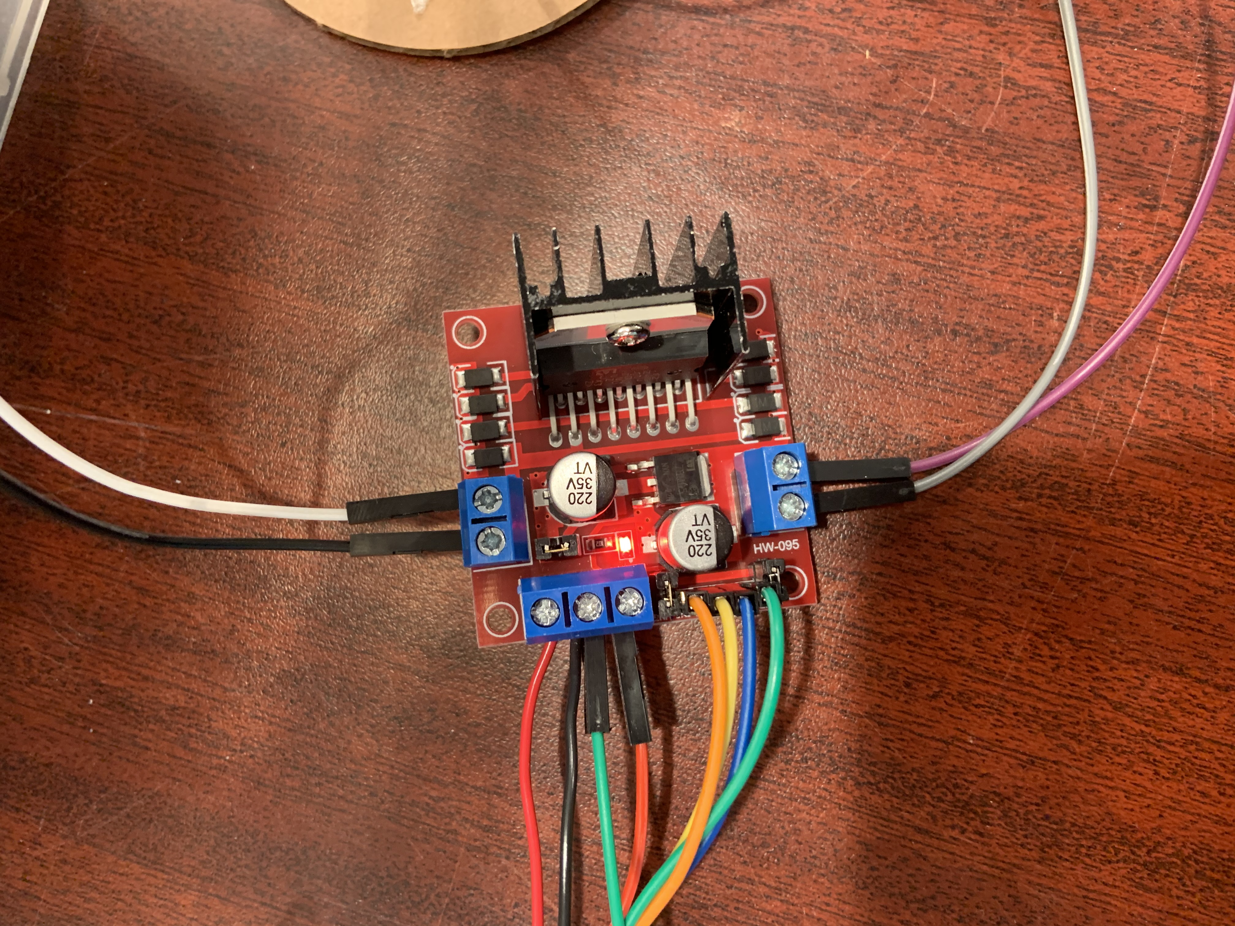
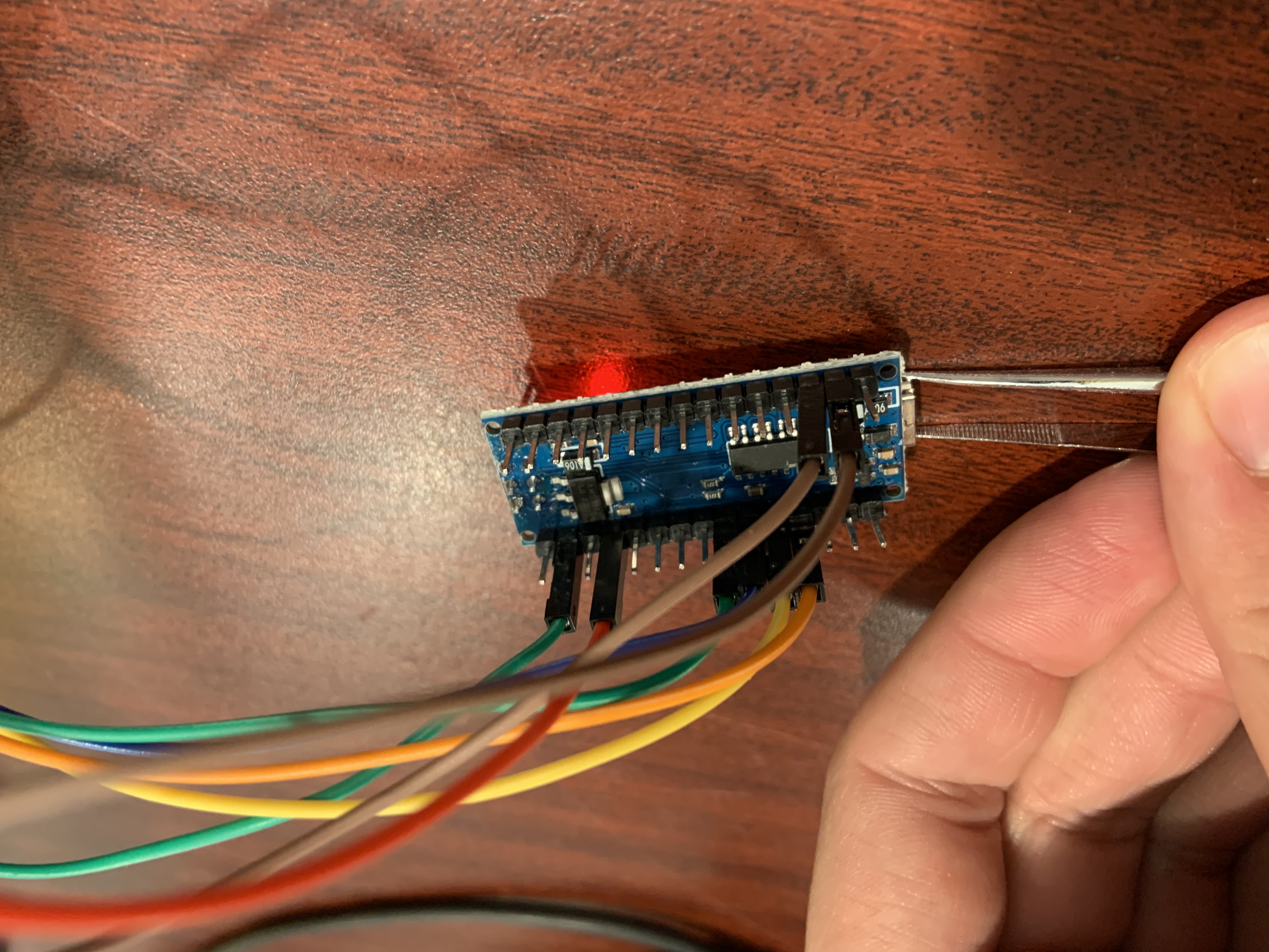
Now with the Arduino Nano programmed and the levitation apparatus set up, it is time to connect everything. First, using 4 male-female jumper cables, connect the Arduino to the L297N motor driver. To connect the Arduino to the driver, connect A0 to N1, A1 to N2, A2, to N3, and A3 to N4. Then connect the 5V supply to the drivers 5V input, and connect the GND to the drivers GND. Finally for the Arduino, connect D10 and D11 to each other using a female-female jumper for synchronized emissions.
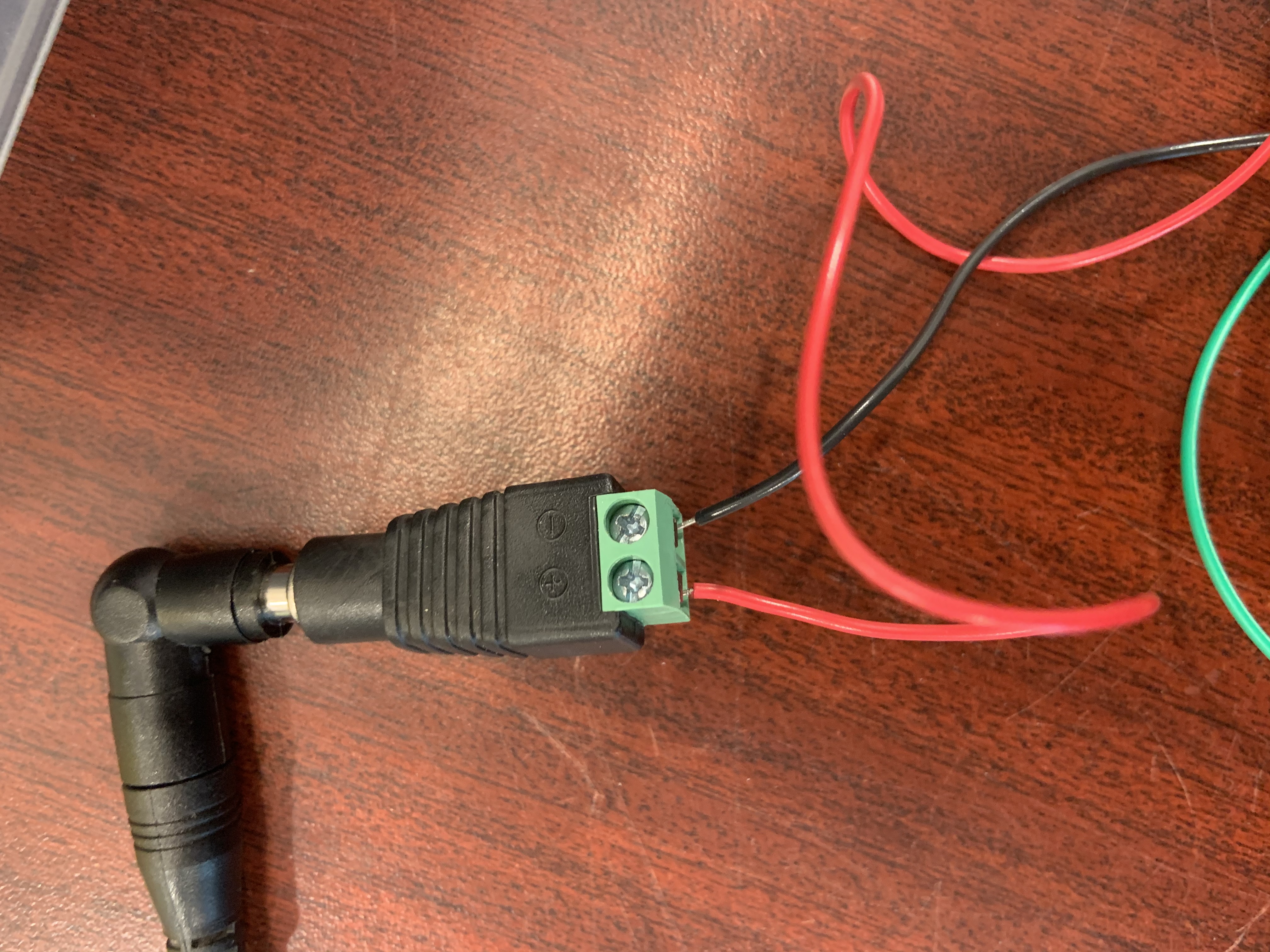
Connect the Female Power Adapter DC Barrel to the 12V power supply male plug. Cut two long wires, one black and one red, then strip both their ends. Using the small screwdriver, connect the red wire to both the positive terminal of the power adapter and the 12V input on the driver. Then connect the black wire to the negative terminal of the adapter and the GND of the motor.
Now your circuit is nearly complete, all that is left to do is connect the motor driver to the transducers. Using 4 famele-male jumper cables, connect one transducer to OUT1 and OUT2 of the driver, and the other to OUT3 and OUT4. Plug in your power supply to a wall outlet, and with tweezers, test with small styrofoam bits whether your levitator is working. Note if not working, you may have the polarities of the transducers mixed up. To fix this, simply switch the wire connections between pins of "one" of the transducers.
About Me (Ryan Curtis)
When I was younger I always had an interest in physics, but being able to grasp it, let alone go to school for it, always felt impossible. I would watch The Big Bang Theory with my family, and while we would laugh at the jokes and situations the characters got themselves into, the physics they would discuss always just felt like it was something that no matter how hard we tried, we would never fully understand. This was my feelings towards physics for most of my childhood, and it wasn't till a trip to Hawaii in Grade 10 that this changed for me. While on vacation with my family for spring break, we took a day tour to the observatories at the top of the Mauna Kea volcano. This day trip was the first time I felt like I really noticed the beauty of space, and the incredible unique opportunities that existed in physics and astronomy. After this trip I decided to rededicate my high school courses to the sciences. I looked into which courses I needed to get into the science departments of Canadian universities, and took as many physics and math courses as I could to not only prepare myself for university courses, but to also see if I could excel in them when I put my mind to it. I had never been an A+ student before, but that was also before I had the drive to become one, especially in the subjects of math and science. It turns out with this new dedication I even surprised myself with how well I was doing, and by the time I was finishing Gr.12, I had been accepted into the Faculty of Science at UBC.
After my first year in Science at UBC, I declared my major to be physics and joined the Physics and Astronomy Department. Through my time in this department I have had many amazing opportunities. The first one being given to me, was a Co-op job at Science World. This 4 month work placement, turned into a part time job for myself for 2 years. The job showed me how fun science communication could be, and how fulfilling it was to teach younger minds about science in a way they could grasp and also enjoy. As a science facillitator, I was given opportunities to do center stage shows, teach visiting elementary school workshops, and visit underserved schools to do after school science programs with their students.
My next work experience was at TRIUMF, Canada's Particle Accelerator Institution. Here I had the privilege of working with two collaborations, the Light only Liquid Xenon experiment (LoLX), and the TRIUMF UltraCold Advanced Neutron Source (TUCAN). The goal of LoLX was to demostrate the capabilities of using liquid xenon to detect particles, with its research having applications to neutrino and dark matter detections. With LoLX I worked with categorizing the background noise in the new light detectors they were using for the detector, called silicon photomultipliers (SiPMs). The TUCAN collaboration is looking to build to largest source of ultracold neutrons in the world, with its source being used to search for a neutron electric dipole moment (nEDM), which would entail that a neutron is not simply a chargless particle, but actually has some imbalance of positive and negative charge inside of it. Under TUCAN, I was tasked with the further construction and application of a Gradiometer, an instrument designed to measured the magnetization of components that are run through it
I had the awesome opportunity to move across the country one summer for one of my Co-ops, which was at SNOLAB. SNOLAB is a particle detector facility in Sudbury, Ontario. Here they burry their detectors in a 2 km deep lab, to block out any background radiation that might trigger them, as they are probing for some of the most elusive particles in our universe. I had the opportunity to work with a new cryogenic testing facility they were building, where my contribution was the constructions of a radon trap, designed to remove radon from the cryogenic noble gases, before they were pumped into the testing facility.
Apart from work, I also have personal projects that I enjoy on the side. One such project is the education physics TikTok account I run with my friend from High School, called @ThePhysicsHouse. We started this account during lockdown when we had nothing to do, and it quickly turned into something larger than we both could have ever imagined. On this account, we both got to create content around topics that we find facinating in physics and math, and we got to see how much people were enjoying it online. It has been a fun project that has cemented our passion for online communication.
.png)
.jpg)
.jpg)