Spectroscopy and diffraction grating
A demonstration and lesson.
By Arne Wind for UBC PHYS 420, 2024-2025.
Overview
The goal of this demonstration is for students to understand how the diffraction glasses handed out at the start of the lesson work. To do this, we will use water waves as an analogue of the light waves that fall on the glasses because they are more known to students. To do this, we will first learn about general properties of waves, then look at the two slit experiment. We will add more slits and look at the interference pattern with simulations. The simulations will be tested with a real world demonstration. When time permits, we will explore what we can do with our new knowledge about separating light.
Physics Concepts
This demonstration was made for students in 3VWO. They are roughly 13-14 years old and do secondary education at the highest level in the Netherlands, preparing them to attend university after they graduate. In Canada this is comparable to students in grade 8 I think. Still, the students will probably be unfamiliar with the majority of the subjects covered in the presentation. The general physics subjects covered are:
- Introduction to waves
- The wave nature of light
- Superposition of waves
- The two-slit / multi-slit interference pattern
- Diffraction gratings
- Emission / absorption spectra
- Spectroscopy and various applications
It is advised that you make yourself familiar with these subjects when doing this demonstration.
The demonstration is mostly designed to briefly introduce all these concepts to the students, not for them to remember / become experts on the matter. If you want, you could split this demo up in multiple lessons where they also do exercises that will help them better understand the subjects they are learning about. For example, when I did this lesson I found that students didn't really get what an interference pattern is and what the graph of intensity as function of time is. You could spend more time on that, but that will prolong the lesson.
Design
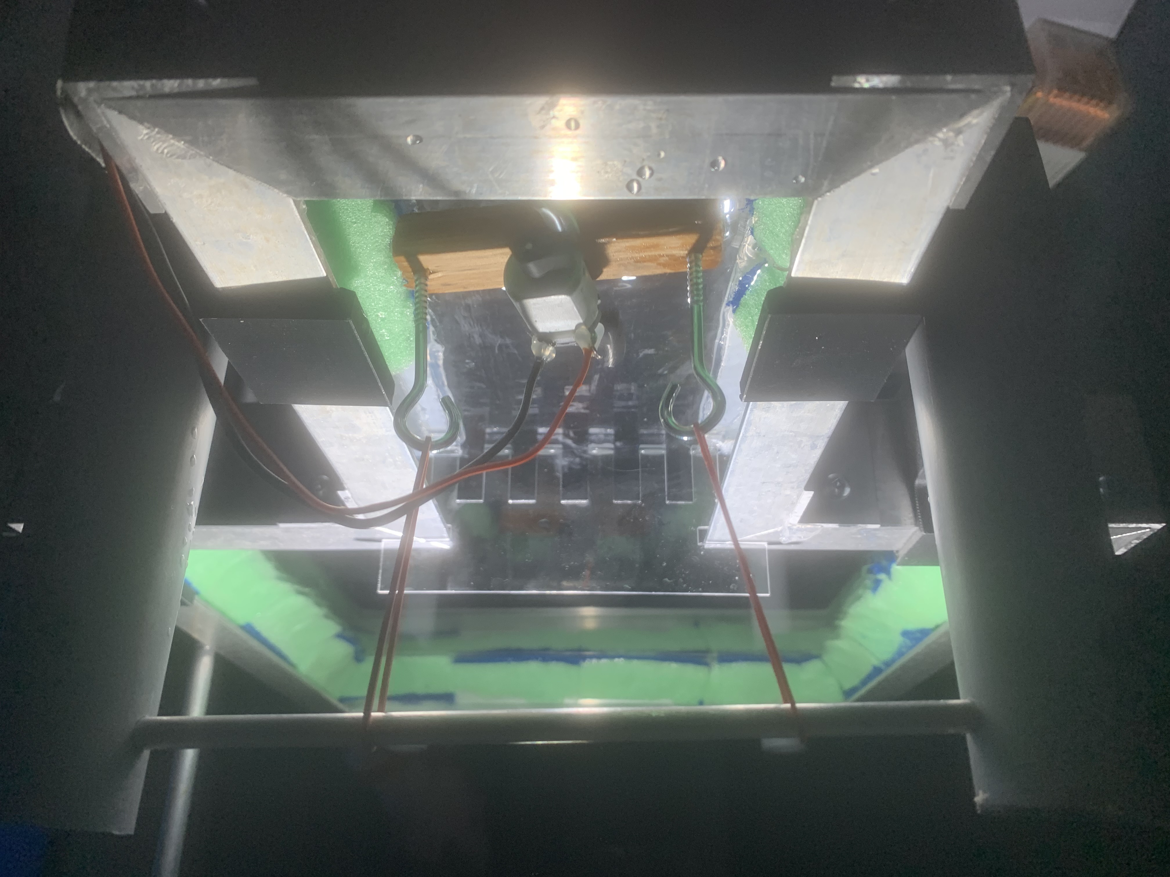
This is a ripple tank, which can show clearly how water waves propagate and interact with barriers. It consists of a couple major components: the tank itself, the legs and the wave maker, and some smaller additional components.
The water tank itself is water tight and has ‘beaches’ made of sponge on the sides that will prevent the waves from reflecting back. It consists of a large part, where the interference pattern of the waves will be visible and a small attachment, where the plane waves will be generated by the wave maker. The bottom is made of plexiglass, so when shining a light though it the wave patterns will be visible. The wave maker is suspended by two elastic bands and will oscillate in the water because the motor rotates an off-centre weight. The plane waves will travel through a diffraction grating, which will cause an interference pattern that is the subject of the demonstration.
The ripple tank has largely been designed in Onshape, an online CAD software. Click here for the link to the project. Should the link not work anymore: here are some of the most important files in Parasolid, ACIS and STEP-formats.

List of materials
- Plexiglass plate, 40 x 60 cm
- C-shaped metal beams, total 2 m
- Metal corner pieces
- Sponges
- Self-drilling screws

- PLA for 3D printing
- 4 x Plastic tubes, diameter 4/3 inch, length 50 cm
- Nuts and bolts

- Small metal cylinder, 20 cm
- 2 x Plastic tubes, diameter 4/3 inch, length 20 cm
- PLA for 3D printing
- Nuts and bolts
- 2 elastic bands
- Small bar of wood, 2 x 2 x 15 cm
- Hooks to screw in wood
- Small pancake motor (DAGU DG01D)
- Wires

Apart from access to these materials, you should have access to a 3D printer, a lasercutter, a solder device and basic tools.
Construction
The setup is comprised of several parts that can be assembled seperately and subsequently joined together. It is designed to be transported relatively compact, as the legs can be detached from the tank. If you really lack space you could also disassemble the tank itself, but you would need to reapply the caulk again later.
Tank
Cut the metal bars, the plexiglass plate (link to drawings) and the sponges in the right shapes. Get self-drilling screws, and using those, pre-drill the metals bars into the right shape of the tank using the corner pieces. Now unscrew them, so they can easily be screwed in again by hand when the caulk is applied.
Put a line of caulk on the upper part of the bottom bar of the C-shaped metal bars, arrange them in the right shape and put the plexiglass plate on top. Press the bars against each other and the plexiglass so everything is in the correct shape.

Using hot glue, attach the sponges to the plexiglass plate in the right shape.


Legs
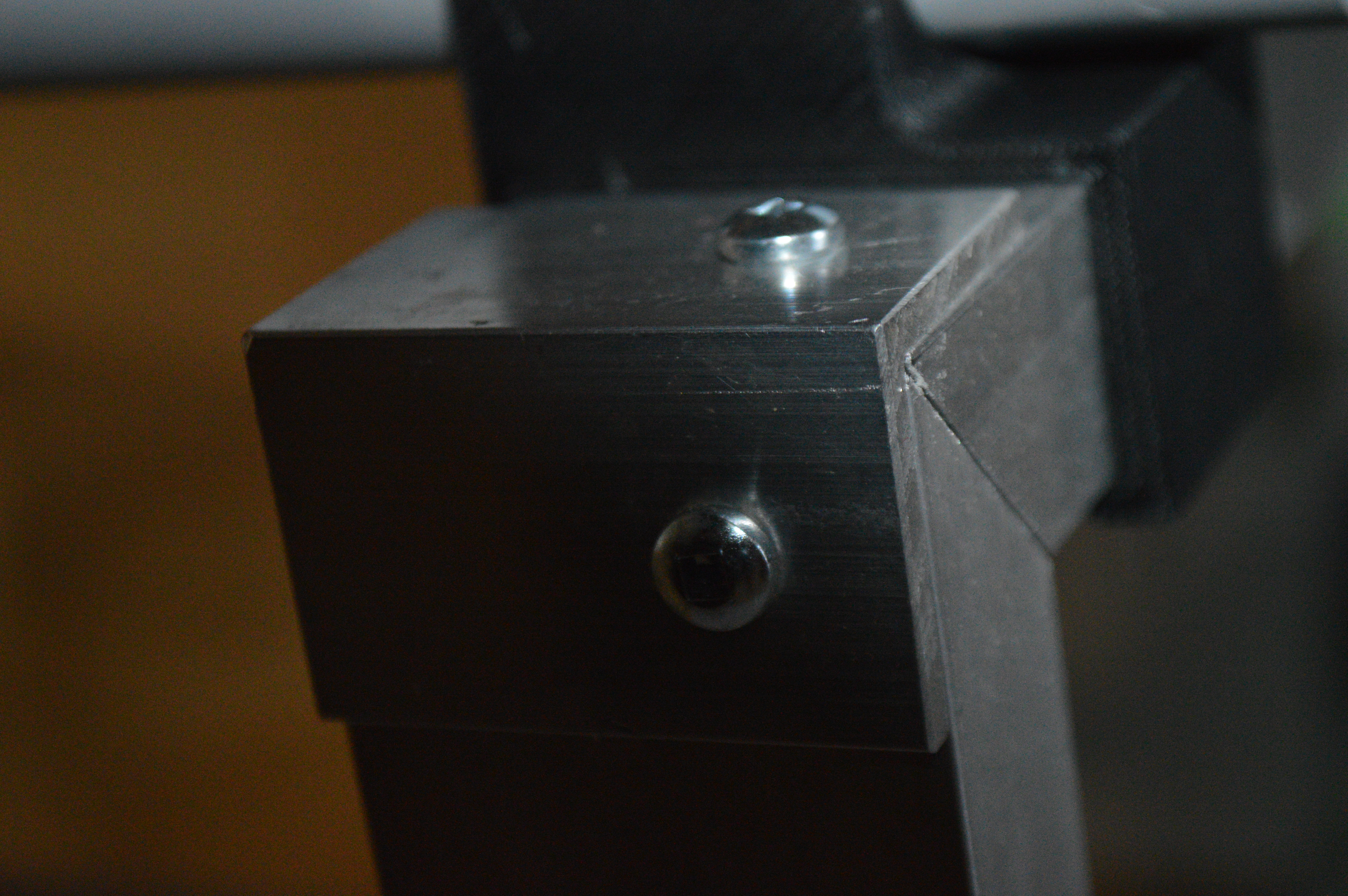
3D print the adaptors. Put a nut and bolt in the designed places for the adaptors. Cut the plastic tubes in the desired length and insert into the adaptors. Tighten the bolt, so the tube cannot move and attach adaptors to the tank. Repeat this at least 4 times for 4 legs.


Wave maker
Get a piece of wood that fits in between the small part of the tank, screw two hooks in at opposite ends. Remove the gearbox from the DAGU motor and glue the motor on its side to the wood. 3D print the 2 attachments for the motors, attach weights (like a screw) to the ends and press them onto the motor pins. Solder some wires to the motors.

Make something similar to 2 additional legs, but a bit shorter (the legs need to be around 30 cm max). Attach these to the tank and make the tubes point upwards. Make two holes in the tubes of the diameter of the small metal cylinder. Using two elastic bands, suspend the piece of wood with the motor of the small metal cylinder.
Final assembly
Now the legs are attached to the tank and the wave maker is in the right position. Connect the motor to a power source. It should work with around 1.5V. To see the wave, mount the torch (or anther light source) above the wave tank shining down. Under the tank, set up a mirror at that reflects the light either at the wall or the ceiling. Cut plastic (preferably something people can see, unlike me who used plexiglass) in the right shape for a diffraction grating and put the diffraction grating in place.
Presentation
The students were extremely enthousiastic about the glasses and the demo, so that will take a while. They seemed to be able to grasp the physics concepts untill we got to the more slits. I think they didn't fully understand what the graphs of intensity as function of position on screen was or why it is important, so you can explain more about that.
The full lesson takes about 80 minutes and is accompanied by a presentation (download here, also available in Dutch). On this page you can find instructions for every slide.
At several points in the presentation are there questions for the students to answer. You can let them discuss the questions for a couple minutes and then write down some answers on the board, but you might find services like Kahoot, Socrative or Mentimeter useful. I used a worksheet (download here, also available in Dutch) in order to make sure they actually wrote down something. I also included a word list of some important terms they might not know so they could look that up during the lesson.
At two points in the lesson, students need a laptop to access a website. If they don't have a laptop you can also do the exercises on a big screen as a class.
Slide 1
Introduce yourself and mention that you will talk about the spectroscopy glasses.
Slide 2
Hand out the glasses. Let the students look through them for a while. This will be accompanied by commotion. Draw their attention to interesting light sources. If possible, bring a hydrogen or sodium lamp, in which the spectral lines are easily visible. A common single wavelength source is a laser pointer. Shine it at the wall and let students look at the point on the wall. After a while, discuss in class what they just saw and explain that you will find out together what the physics behind this is.
Slide 3
To know how the glasses work, we zoom in. We see the very small lines, which we call a diffraction grating. To simplify the situation, we first look in one direction (only vertical lines). We have to examine what happens when light hits this diffraction grating.
Slide 4
To understand what happens when light hits the diffraction grating we need to know that light is a wave. The details of what kind of wave this is are unimportant, but you need to know that it behaves like any kind of wave. That property of waves will be used to explain what we see through the glasses.
Slide 5
In this slide you will revisit / learn about some important properties of waves.
Slide 6
In this slide you can explain that we will look at what happens when water waves hit a diffraction grating. Because waves behave the same, understanding what happens with water waves will also teach us what happens with the light waves. The picture in the top right can also be used for the previous slide.
Slide 7
Explain the really important phenomena of constructive / destructive interference. Refer back to slide 5, question 4.
Slide 8 - 9
This slide will first explain what happens in two-slit interference. Take some time to let the students take in what is seen in this diagram. The blue and purple lines show where the peaks of the waves originating from slits S1 and S2, at some fixed moment in time. The black dots correspond to places where peaks align with peaks, resulting in constructive interference. The white dots correspond to destructive interference, where peaks line up with troughs. If you look at the bigger picture, you see lines of black and white dots. If you then look at a fixed vertical line in space and let time play, you would see that at some points, you see big oscillations and at some points you see small / no oscillations. The height of the oscillations is graphed with the 90 degrees rotated graph on the slide. Make sure that the students have some idea of what is going on in this slide and what everything represents. This might take some time.
Slide 10
Let the students get their laptop to play with a two slit simulation themselves. First explain how the simulation works, then let them play with it. Hopefully they see the aspects from the previous slide. An image on this slide helps them to see the regions op destructive interference.
Slide 12 - 14
Now we will explore what happens when we add more slits (N slits). Show the students this formula, but assure them that while it looks scary, they don’t have to remember it. In slide 14 you have a visual aid to explain what all the parameters in the formula mean.
Slide 15
Let the students get their laptop, open desmos. Explain how desmos works and let them play with the formula themselves. After a while discuss what happens when you change various parameters in the formula. The most important parameter is the wavelength. They should know that changing the wavelength means the peaks will be at different angles.
Slide 16 - 17
At this slide you get the physical demonstration. Make sure everyone can see what is going on (make the room as dark as possible) and turn on the wave generator. Switch between different diffraction grating to see if you can observe changes in the location of the peaks.
I found that a mirror reflecting the light back up did the job well, displaying the image on the ceiling of the classroom, which was well visible for students in their chairs. You can move the light source out of the way so you don't see its shadow in the image of the waves. You can also try to vary the wavelength by making the motor spin faster or slower, but I found this to be very difficult. If you make it spin too fast it will splash water and ruin the pattern.
Slide 18
Using the knowledge we just gained, we now understand what happens in the glasses. First explain that wavelength of light is the same as its colour and that different wavelengths means different diffraction of the light rays.
Slide 19 - 20
Introduce the concept of spectroscopy. If you are out of time, skip the part where they think about applications themselves.
Slide 21
Basically explain that every molecule, because of quantum mechanics, has a unique absorption and emission spectrum that can act as a finger print.
Slide 22
Explain how you would see an absorption and an emission spectrum.
Slide 23
Show the emission spectrum of a sodium lamp, which they may have seen already if you brought it to class.
Slide 24 - 27
Let students think about useful ways to apply spectroscopy in the real world. Then showcase some real world applications.
Slide 28
If you have time, show some other ways light can be separated. If possible, you can bring a prism.
Contact
For any questions or comments, please feel free to contact me by email at don't contact me because I don't want my email on internet.
For more information about the PHYS 420 course and other demo ideas, visit the course resource page.