![]()
Build It!
![]()
Materials:
|
Remote control car/truck and necessary batteries | |
|
photo transistor (light sensor) | |
|
9 V battery | |
|
10.6 ohm variable resistor | |
|
NPN transistor | |
|
MOSFET | |
|
push button | |
|
2 switches | |
|
2 10 kohm resistors | |
|
coloured tape | |
|
flashlight and stand | |
|
measuring stick |
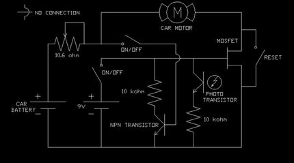
The demonstration relies on an interrupt circuit, pictured below, which cuts the power supply to the motor when the light is passed. Click here to see a larger circuit schematic.
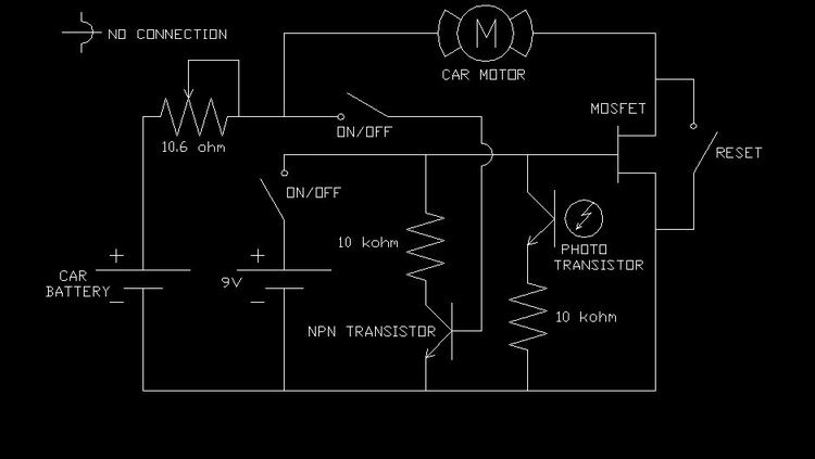
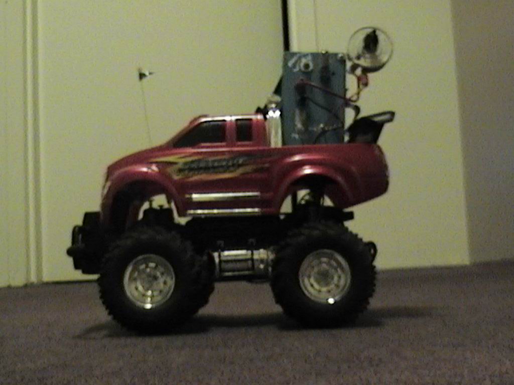
When the switches are open, the circuit is essentially bypassed, and the car runs normally. When the switches are closed the light sensor may stop the power supply when stimulated. The circuitry and batteries can be mounted in a box and placed in the trunk or truck bed, as shown below.
To minimise error, a starting position should be marked in tape and used. This will ensure the car takes a similar path on each run, and therefore the error in the zero point will be minimised. Also, depending on the sensitivity of the light sensor, the zero point may not be directly in front to the flashlight beam. Roll the truck in front of the light and observe exactly where the power is cut - this is your zero point.
![]()