Catcher (Conversion of Plotter)
 The modification of the plotter to make the catcher is
fairly straightforward. Most of the base and electronics is left intact. The
traveling arm that holds the plotting pen and moves it in the Y direction is
removed to be used on the ramp drive (see photo). There are about 7 wires that
go from the Y drive circuit board to the Y drive servo on the moving arm. These
wires must be cut at a convenient location and extended to the Y servo's new
home on the launch ramp. A bonus from this modification is the long flexible
sheath that the Y drive wires were originally protected by as the traveling arm
moved. This sheath is actually a long spring that is now used to counterbalance
the weight of the moving portion of the launch ramp so the servo can move it
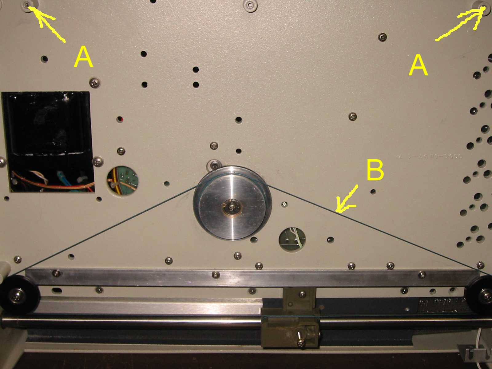
more easily. The pulleys at location "A" are removed for the ramp
drive and the pulley wire "B" is shortened to go around only the
lower pulleys as shown. The pen lift solenoid is also removed, to be used later
as part of the ball release. No modifications are necessary to the electronics
under the deck. The power supply is used as a clean source of +5V for the D/A
interface.
The modification of the plotter to make the catcher is
fairly straightforward. Most of the base and electronics is left intact. The
traveling arm that holds the plotting pen and moves it in the Y direction is
removed to be used on the ramp drive (see photo). There are about 7 wires that
go from the Y drive circuit board to the Y drive servo on the moving arm. These
wires must be cut at a convenient location and extended to the Y servo's new
home on the launch ramp. A bonus from this modification is the long flexible
sheath that the Y drive wires were originally protected by as the traveling arm
moved. This sheath is actually a long spring that is now used to counterbalance
the weight of the moving portion of the launch ramp so the servo can move it
more easily. The pulleys at location "A" are removed for the ramp
drive and the pulley wire "B" is shortened to go around only the
lower pulleys as shown. The pen lift solenoid is also removed, to be used later
as part of the ball release. No modifications are necessary to the electronics
under the deck. The power supply is used as a clean source of +5V for the D/A
interface.
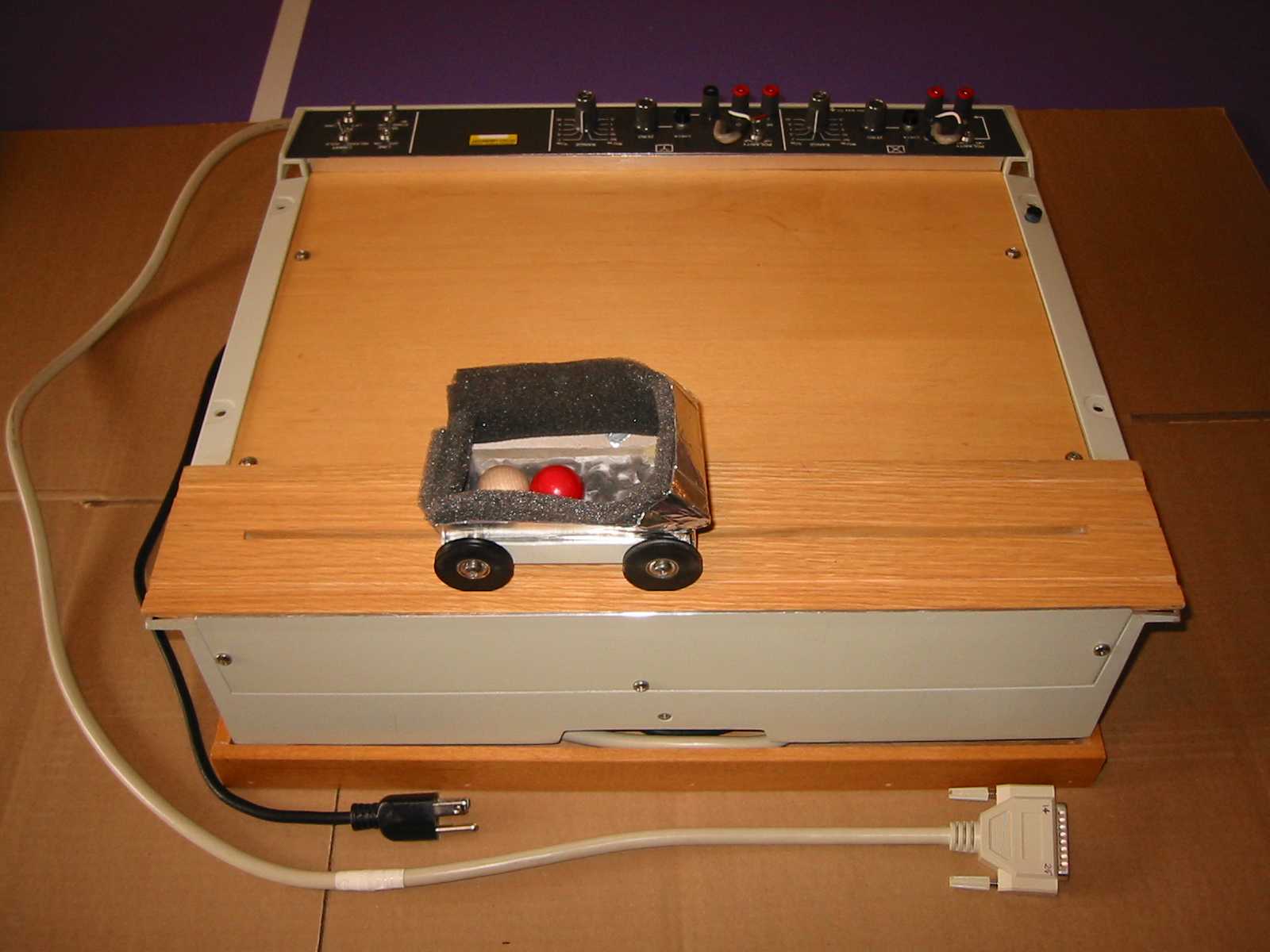
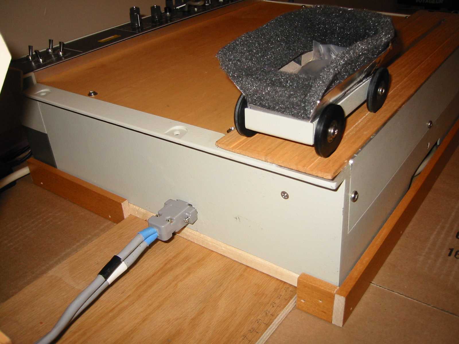
The cart is driven by a long screw that goes
through the bottom of the cart, through a slot in the wooden track, into the X
drive block visible in the photo above. The photos below show the wooden deck
of thin (1/8") plywood used to cover the pulleys and gears. Another piece
of thicker (1/2") wood is used for the cart track that keeps the catcher
cart running back and forth in a straight line. The cart was built from some
aluminum salvaged from the plotter and has a lightweight fairing that helps keep
the ball from bouncing out. Also clearly visible is the location of the cable
connection between the launch ramp and the catcher as well as the construction
of the ramp base sliding under the catcher base.
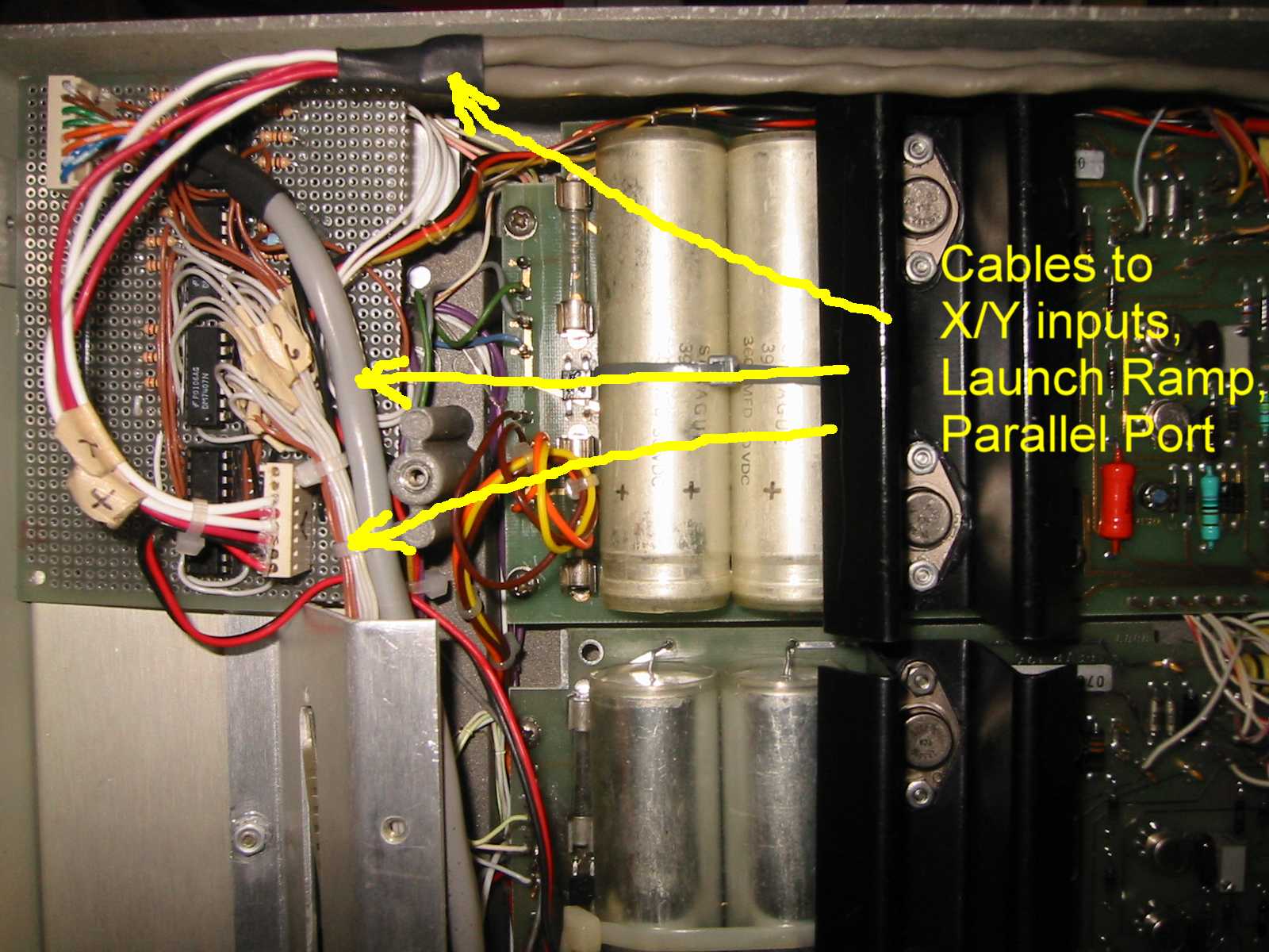
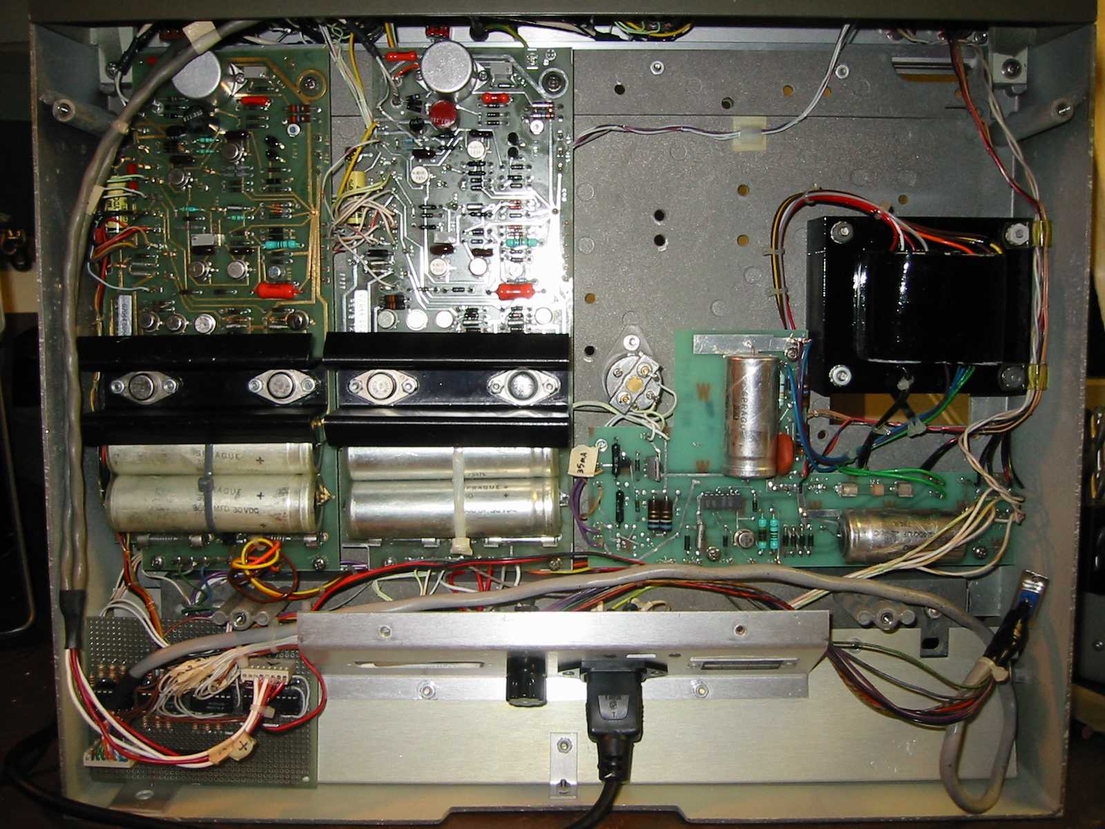
Once the D/A interface is complete it can be
mounted under the deck of the plotter as shown in the photos below. There are
four cables connected to the circuit board. The red and white wires are the
analog outputs from the D/A chip that go through holes drilled beside the
binding posts on the top deck of the plotter. The gray cable first combines
with the 7 wires from the Y servo control and then terminates at the 15 pin
female connector on the side of the plotter that mates with the connector/cable
on the launch ramp. The bundle of white and brown wires terminates on a 25 pin
connector that mates with a standard printer cable from the PC. The remaining
cable is the red/black pair that brings the +5V supply from the plotter's
powers supply circuit board.