 Launch Ramp
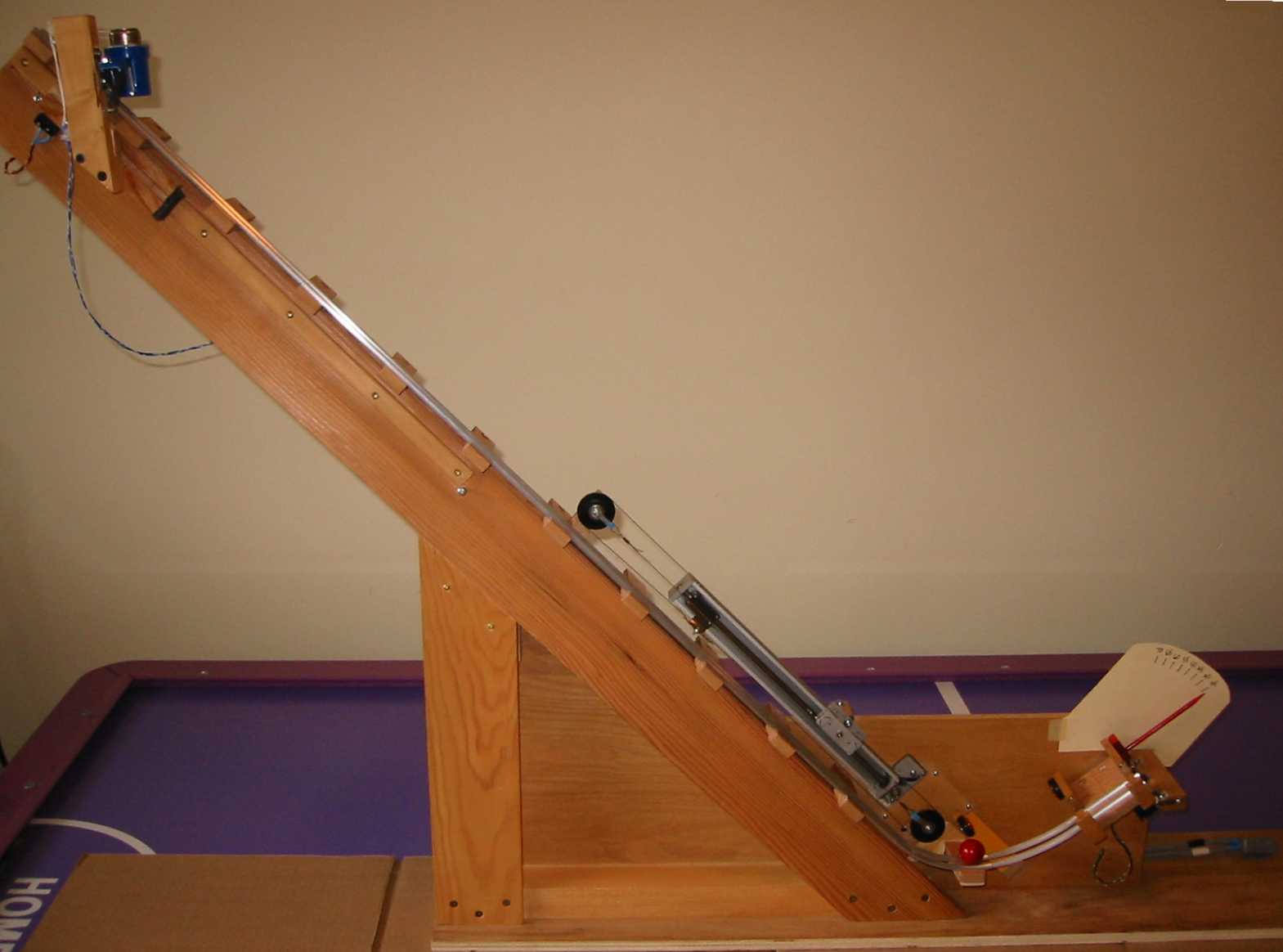
As shown in the picture to the right, the
launch ramp is constructed a bit like a railway track with an automatic ball
release at the top and a curved launch section at the bottom.
Rails
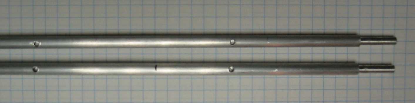 Two 1/4" aluminum rods are used to make the rails. In the picture
to the right you can see that the lower ends of the aluminum rods are machined
to fit snugly into 1/4" polyethylene tubing which forms the curve to the
final straight track segment. Holes are also drilled and tapped to accept M3
screws at 10 cm intervals along their length. The lower ends of the aluminum
rods are bent upwards in a 10 cm radius curve through an angle of 60 degrees.
This gives the rolling ball its initial upward direction onto the curved
polyethylene tubes.
Two 1/4" aluminum rods are used to make the rails. In the picture
to the right you can see that the lower ends of the aluminum rods are machined
to fit snugly into 1/4" polyethylene tubing which forms the curve to the
final straight track segment. Holes are also drilled and tapped to accept M3
screws at 10 cm intervals along their length. The lower ends of the aluminum
rods are bent upwards in a 10 cm radius curve through an angle of 60 degrees.
This gives the rolling ball its initial upward direction onto the curved
polyethylene tubes.
 Ties
Ties
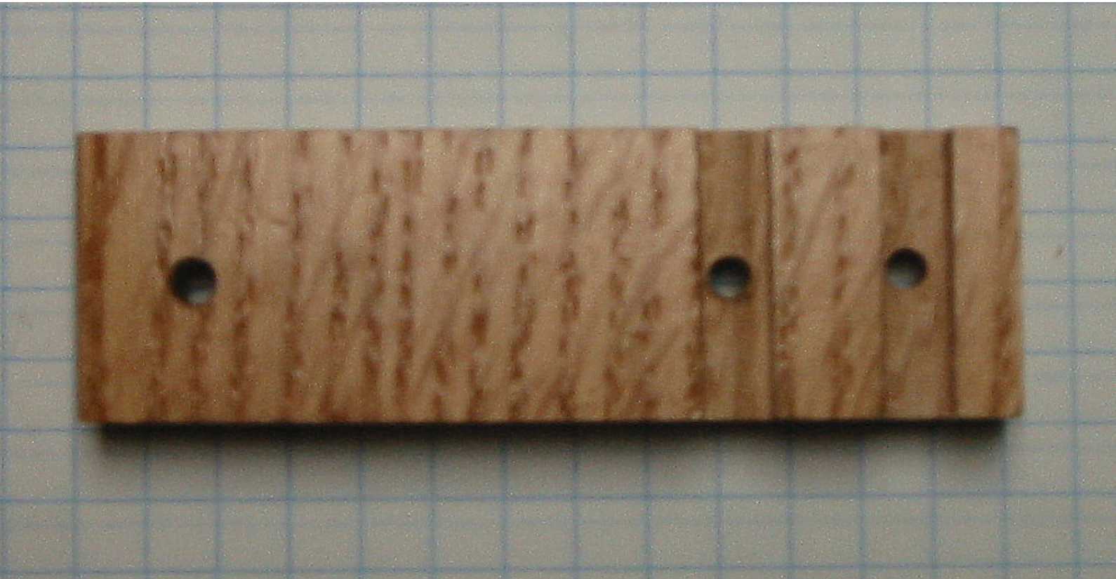
The rods are mounted on a series of wooden
ties (see photo). The ties have slots cut in them to keep the rods at a fixed
distance apart (see photo). Screws go through the holes in the tie and into
threaded holes in the rods, fixing them in place.
Ramp Movement
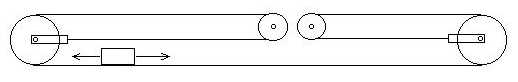
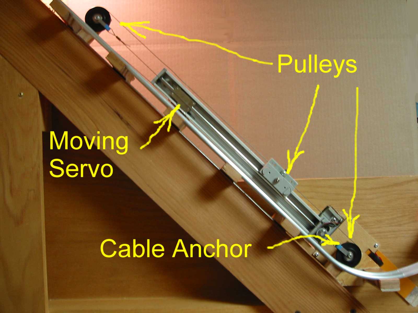 The ramp is moved up and down using the Y servo from
the plotter geared down 3:1 via a pulley arrangement as shown in Photo 5. The
pulleys are those salvaged from the plotter. These are bearing mounted pulleys
that provide minimum load on the servo. The actual arrangement of the pulleys
is shown in the diagram below. The servo and small central pulleys are fixed to
the ramp support. The large black pulleys are fixed to the moving ramp and
actually move up and down with the ramp.
The ramp is moved up and down using the Y servo from
the plotter geared down 3:1 via a pulley arrangement as shown in Photo 5. The
pulleys are those salvaged from the plotter. These are bearing mounted pulleys
that provide minimum load on the servo. The actual arrangement of the pulleys
is shown in the diagram below. The servo and small central pulleys are fixed to
the ramp support. The large black pulleys are fixed to the moving ramp and
actually move up and down with the ramp.
Ramp Angle
 To allow the launch angle to change, the entire rail
assembly is mounted to a 45 degree support beam by means of a sliding drawer
track purchased from the local hardware store. This allows the rail to move up
and down along the support, driven by the servo and pulley arrangement. The
weight of the rail assembly is balanced by a long spring (also salvaged from
the plotter) mounted on the back of the support.
To allow the launch angle to change, the entire rail
assembly is mounted to a 45 degree support beam by means of a sliding drawer
track purchased from the local hardware store. This allows the rail to move up
and down along the support, driven by the servo and pulley arrangement. The
weight of the rail assembly is balanced by a long spring (also salvaged from
the plotter) mounted on the back of the support.
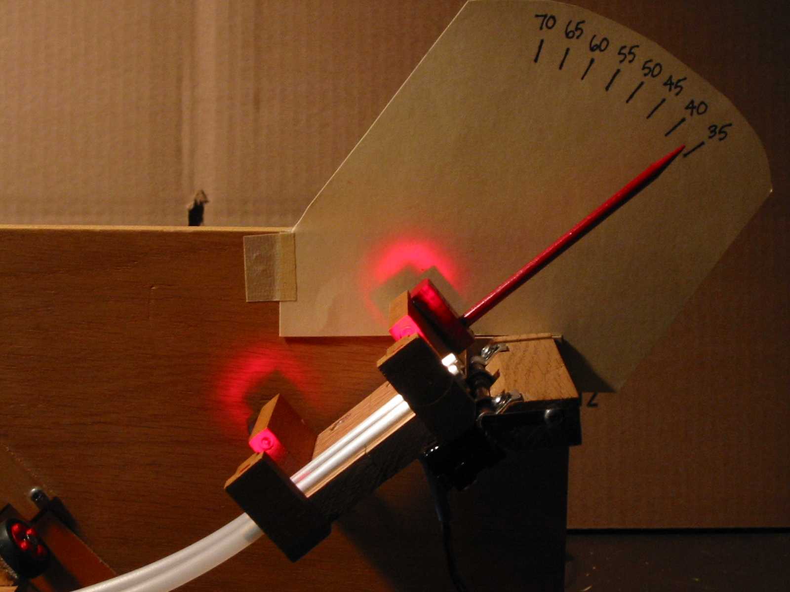
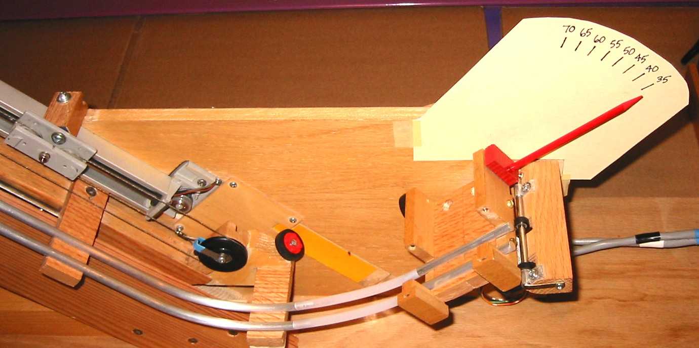 The variable launch angle is achieved by hinging the
final 6cm segment (containing the speed gate) at its end point so that as the
ramp moves, the angle changes (see photo, right). The LEDs and photo sensors
are also easily visible in this picture. The hinge mechanism was salvaged from
the head positioner out of an old 5" floppy drive. It is important to use
hardwood mounts and good bracing for the hinge because of the large amount of
stress placed on it when the ramp pulls back for the lower launch angles. You
can also see an old Lego wheel that is attached to the moving ramp and runs
against the support plywood stabilizing the lower end of the ramp and aligning
it properly with the hinged launcher segment. It is very important when
assembling the launch ramp to maintain careful alignment of the pieces.
The variable launch angle is achieved by hinging the
final 6cm segment (containing the speed gate) at its end point so that as the
ramp moves, the angle changes (see photo, right). The LEDs and photo sensors
are also easily visible in this picture. The hinge mechanism was salvaged from
the head positioner out of an old 5" floppy drive. It is important to use
hardwood mounts and good bracing for the hinge because of the large amount of
stress placed on it when the ramp pulls back for the lower launch angles. You
can also see an old Lego wheel that is attached to the moving ramp and runs
against the support plywood stabilizing the lower end of the ramp and aligning
it properly with the hinged launcher segment. It is very important when
assembling the launch ramp to maintain careful alignment of the pieces.
 The Speed Gate
The speed of the ball is detected by
the two optical switches in the speed gate. The optical switches are closed
(current flows) when the LED shines on the photo detector. When a ball passes
between the LED and the detector the optical switch opens and current flow
stops. The status of the two switches are converted to logic levels and sent to
the computer via the parallel port as SpeedBit1 and SpeedBit2. The computer
program can then detect the transit of the ball through the gates as four time
stamps (enter gate 1, leave gate 1, enter gate 2, leave gate 2) accurate to 1
millisecond. The speed of the ball as it leaves the ramp is determined from
this data.
 Ball Release
The ball release uses the plotter pen lift
solenoid to kick the ball out of the bottom of a tube. As can be seen in the
picture on the right, the tube is hinged and spring loaded to resist releasing
the ball until the solenoid is activated. The solenoid is driven by a power
transistor that is pulsed via a logic signal from the PC. For circuit details,
see the circuit
diagram.
There are two additional micro switches
incorporated into the launch ramp. One senses when the ball release is at the
top of its variable height range (just visible in the picture on the right).
The other senses when the launcher and catcher are pushed tight together so
that the catcher is at its closest point to the end of the launch ramp. These
are not really necessary to the operation of the demonstration but are used by
the software to detect "impossible to catch" setup parameters. That
is, if the ball release is at the top position, the launch angle is less than
50 degrees and the catcher is right next to the launch ramp, the ball will fly
right over the end of the catcher!
 Support
Structure
Support
Structure
The remaining construction on the ramp is
mostly for supporting and reinforcing the launcher. The entire support is
mounted firmly on an 80cm by 20cm plywood base. The right end of this base fits
into a slot in a wooden base that the catcher sits on allowing the distance
between the end of the ramp and the left side of the catcher to be aligned and
set to the correct distance.
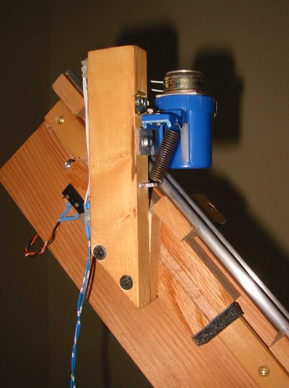
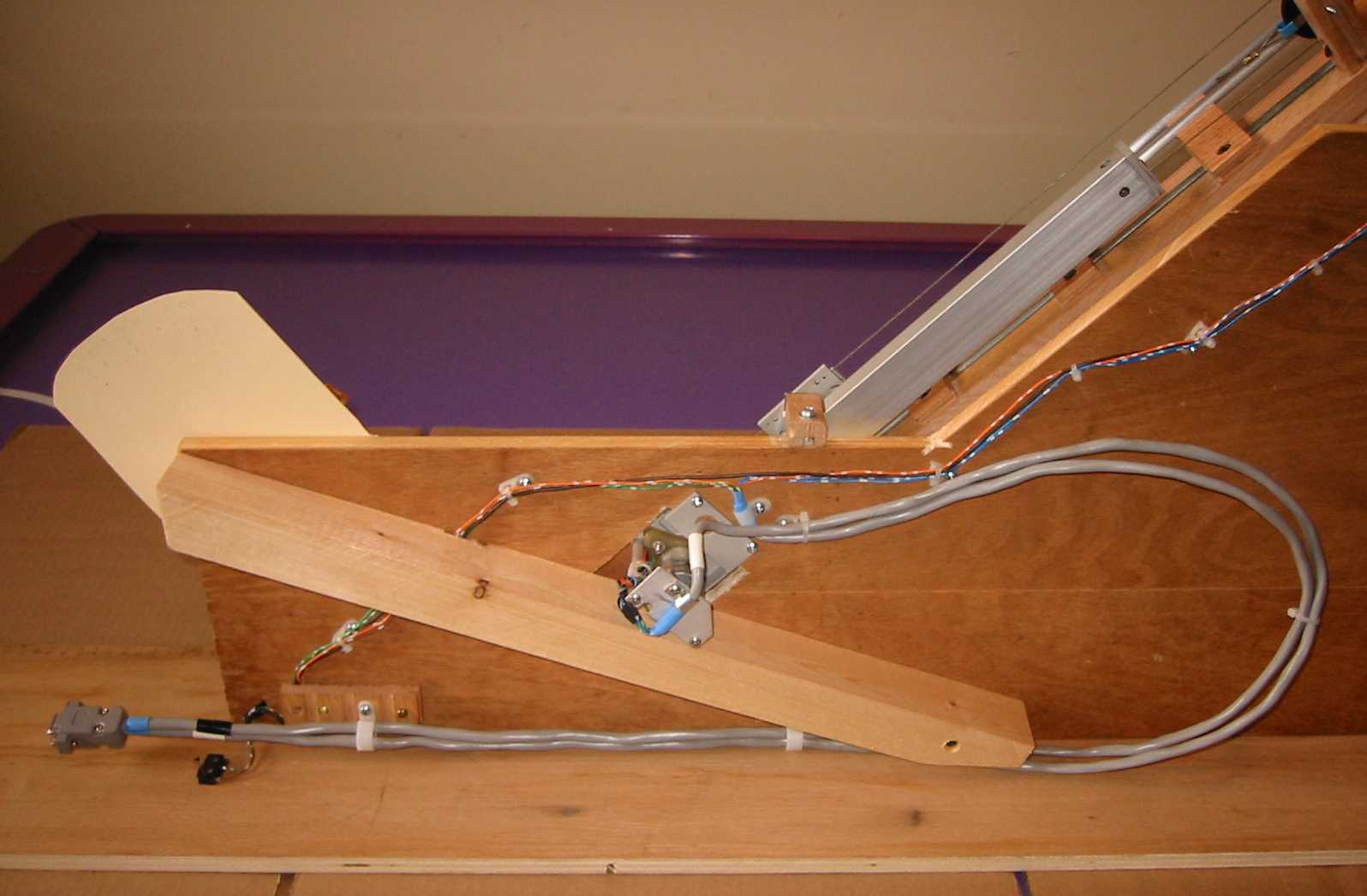
The picture at right shows the back side of
the ramp support structure including the Y servo mount, the connector and
associated wiring. The second microswitch that detects the ramp at its closest
proximity to the catcher is also visible attached to the base near the cable
connector. The lighter coloured diagonal brace stiffens the plywood that the
ramp and hinged speed gate are mounted on to prevent bending when the ramp is
moved to its highest point and pulls the hardest on the hinge.