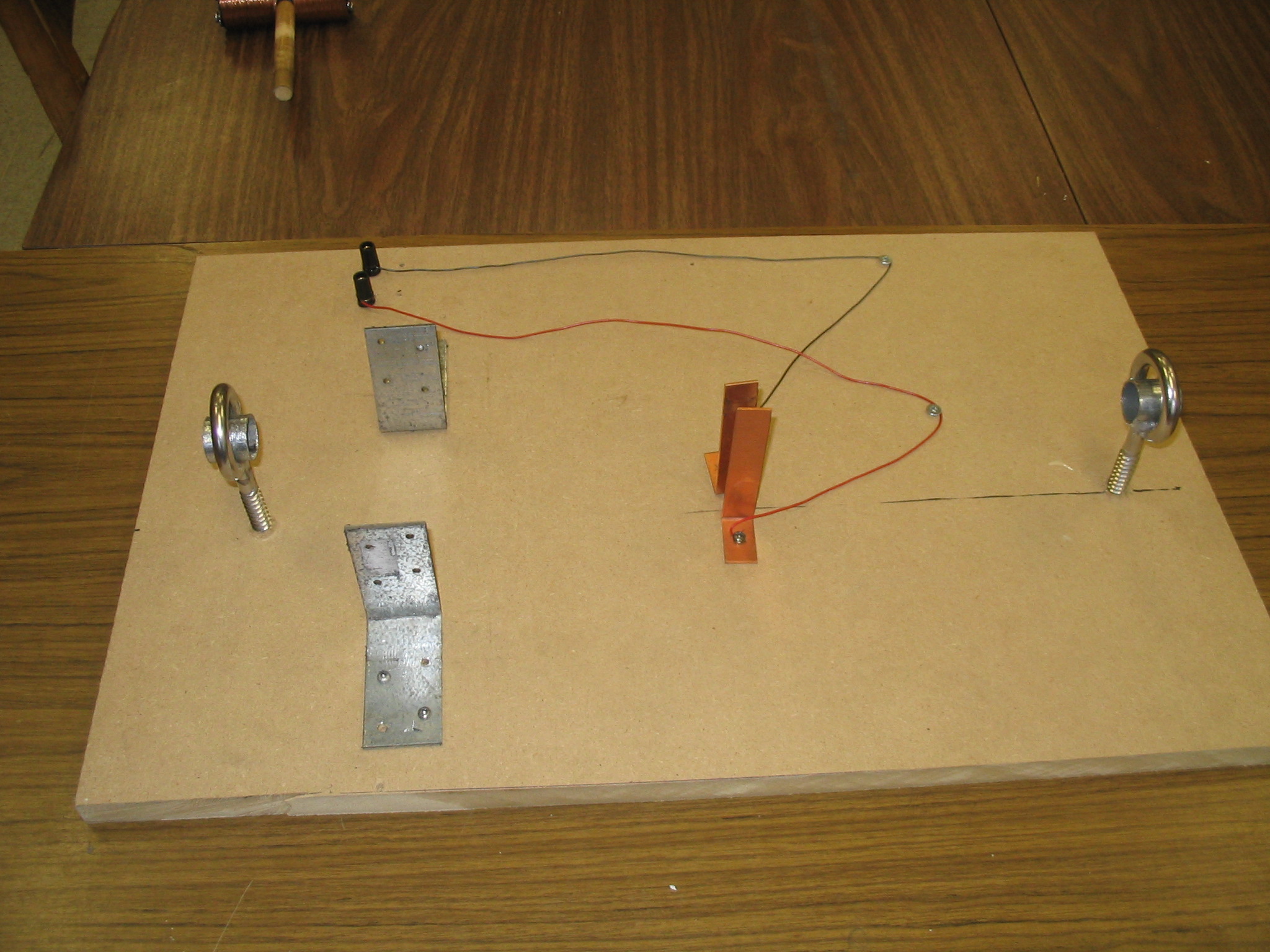
1. This is the base of the electric motor that I made. Consisted of a wooden board, two ring stands, two copper plates, two L-shape clips that are used to hold the magnet, and wires.
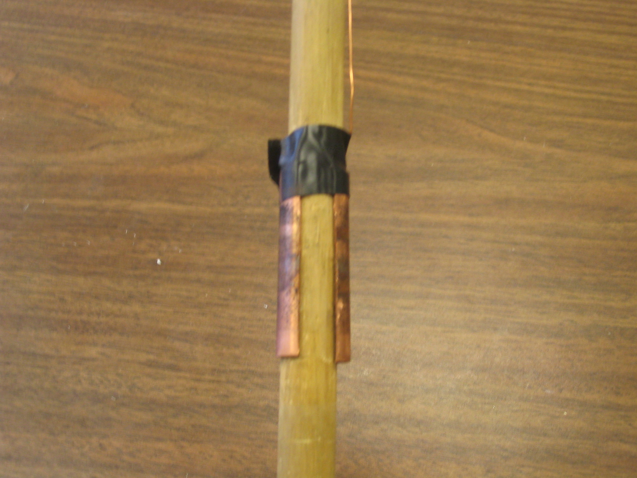
2. The Commutator, is two pieces of half ring copper plate that are attached on the side of the rod, which is in contact with the brush.
3. The brush, made of 2 copper plates what are connected to the power supply through wires and are constantly in contact with the commutator.
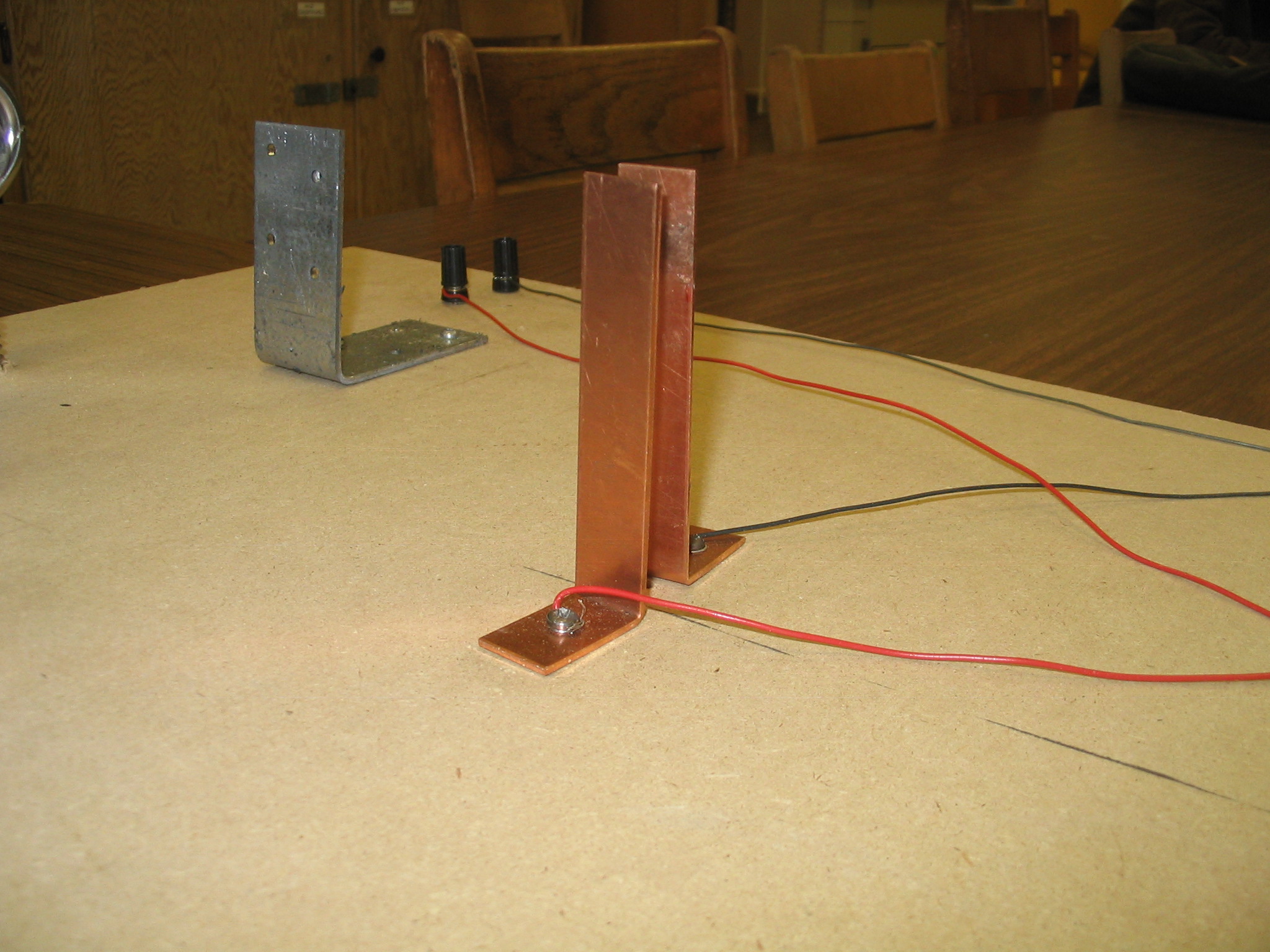
4. Two huge magnets that stands beside the coil of wire as it rotate, providing the permanent magnetic field in the motor.
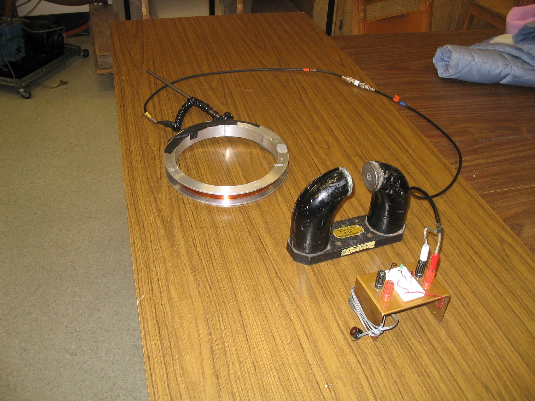
5. The Top view of the DC electric motor.
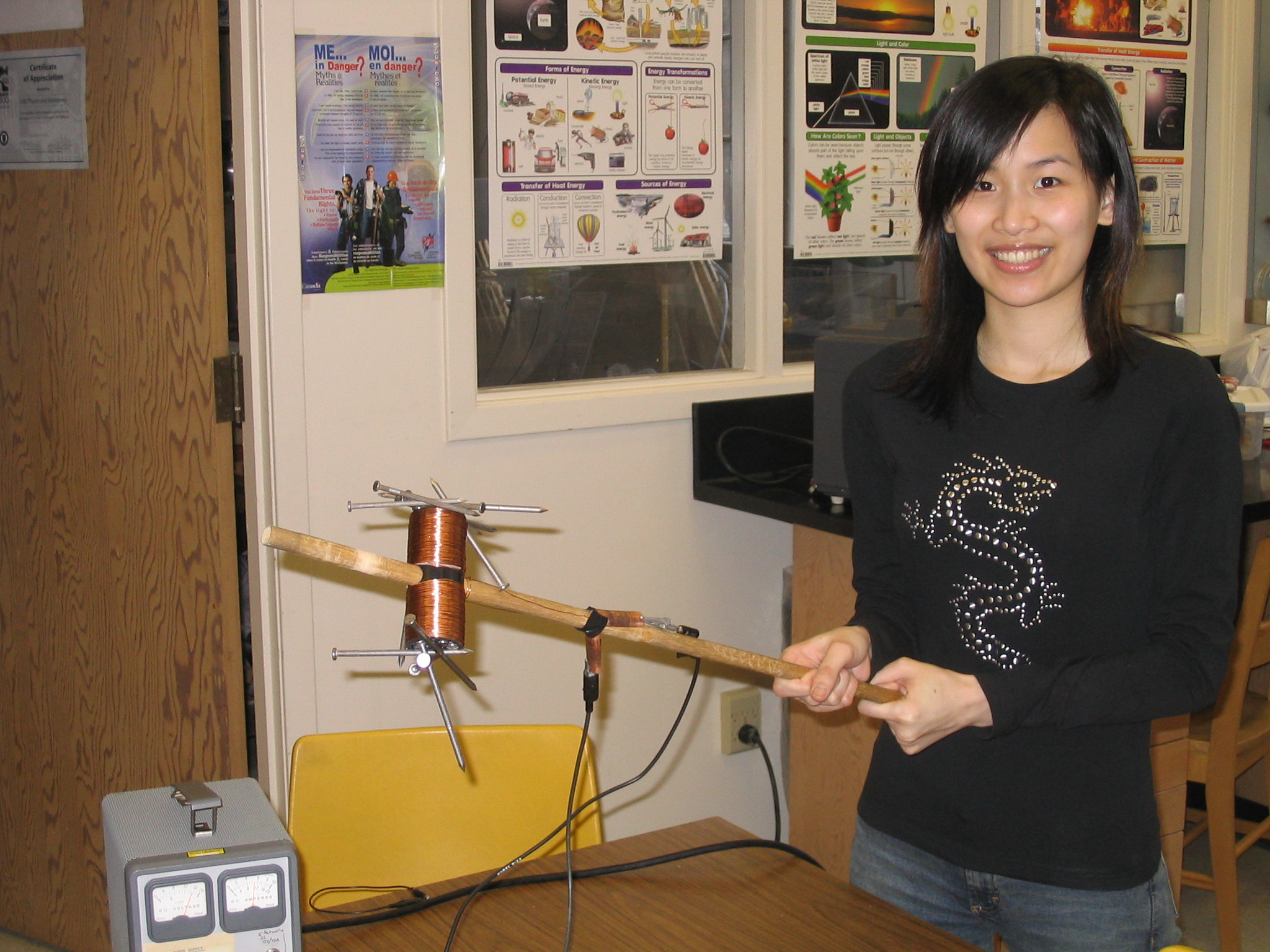
6. This is the center rod (rotating axis) of the DC motor. This is made of a wooden stick, a plastic pipe (around 5 cm in diameter and 12 cm in length), about fifteen 12 cm long iron nails in the middle and 30 m of heavy gauge magnet wire coil around the pipe. This is also known as an electromagnet. This is the main component that provides the magnetic force which opposes the permanent magnetic field, which then causes it to spin.
7. As you can see in the following two graphs, the electro magnet is hooked up to a power supply and becomes a electromagnet that attracts many nails.
8. Jenny Weng who is amazed with the number of nails that this electromagnet can hold.
9. This little DIY motor is for the students to make during the presentation. This is a fairly simple project which can be done in about 10 ~ 15 minutes. The detail of how to make the motor is described in the PowerPoint slide attached in the lesson page.
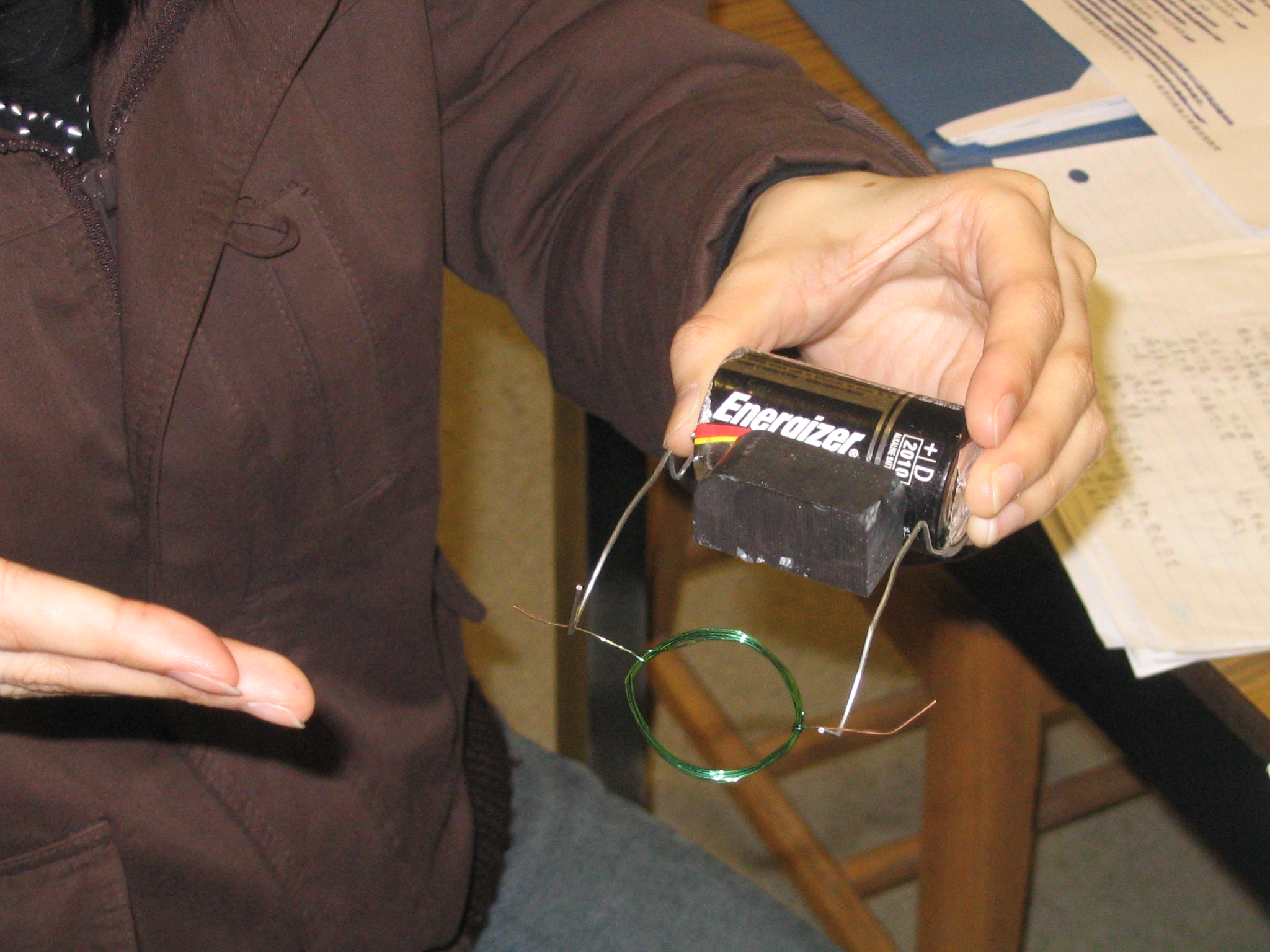
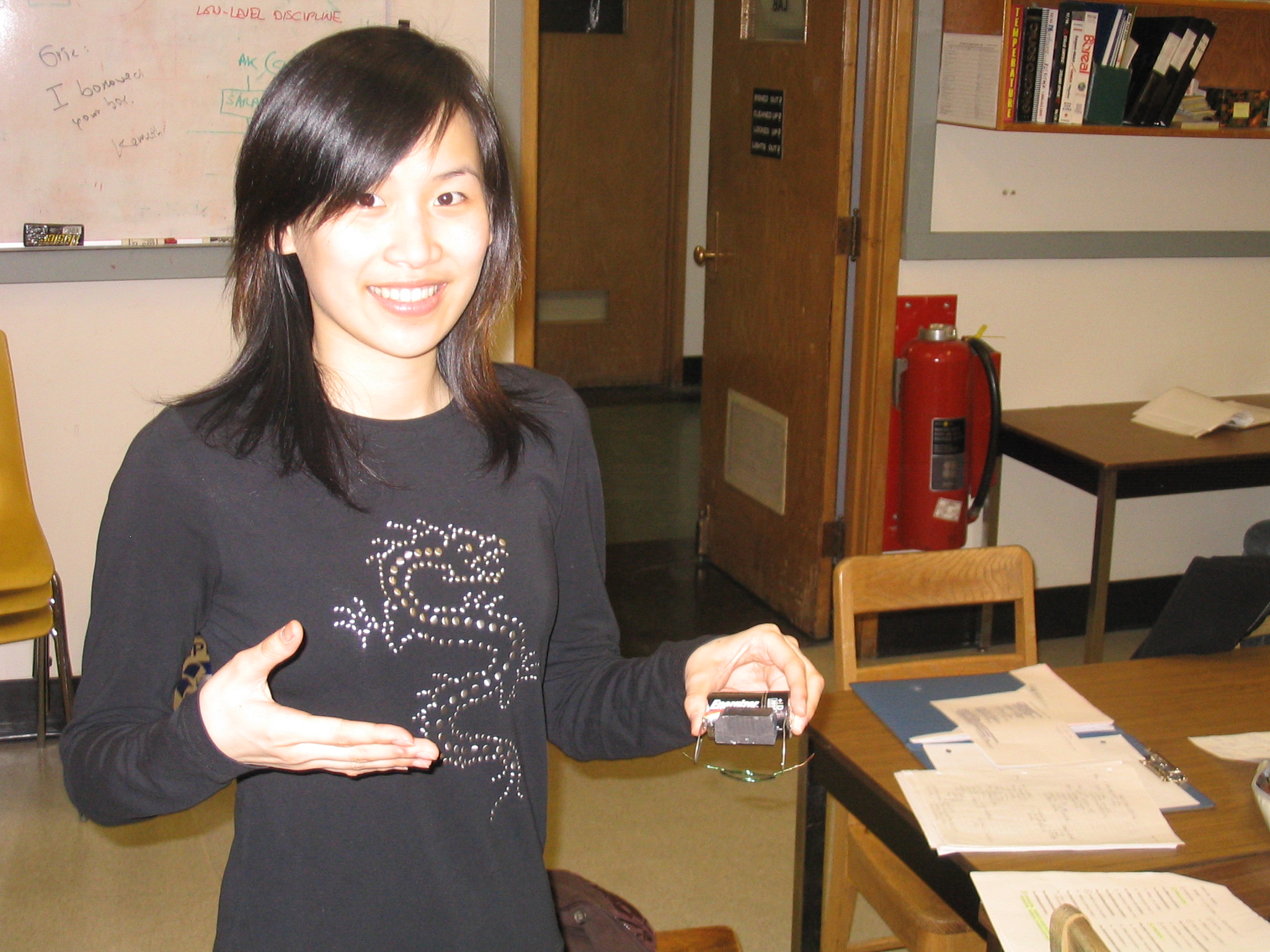
10. Jenny Weng, as usual, is again amused with this little turning machine that she is holding. She is also very amazed that this can be done in just 10 minutes.
11. A generator demonstrations made by Jason Chow in the UBC Physics Outreach lab. He kindly let me borrow this demo to show my class that as the coil of wire passes through the magnetic field, it will produce current to light up the LED light. Also, the generator concept is also demonstrated to the class by rotating the center rod of the motor built above and the students can read of the current reading shown on the multimeter that is connected to the brush of the motor.