Instructions on Creating Project

The following instructions are based very loosely on the 5-minute video, linked here. If at any point the instructions for my current instructions seem too confusing, please refer to Reflections where I attempt to discuss why I made the design the way it is, and what could be improved upon if I am to make this again.

INGREDIENTS
Materials
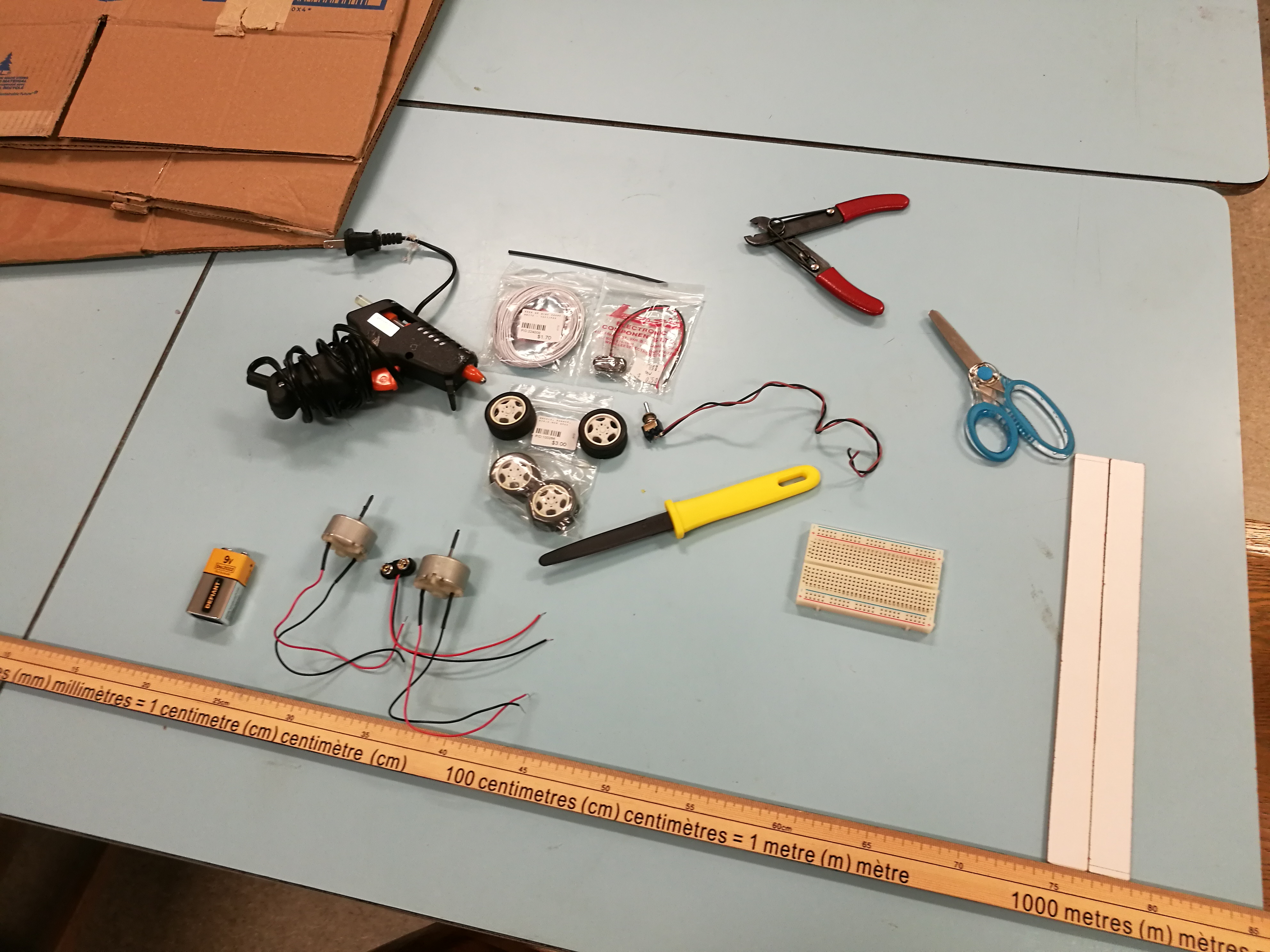
	- Access to 3D-printer
	- Access to TinkerCAD (free, online)
	- Cardboard boxes
	- 1x switch
	- 1x battery connectors
	- 2x 9V battery (second one is a spare)
	- 2x DC Motors (optionally: recommended at radius 16mm, height 25mm)
	- 2x toy car wheels
	- 1x shrink wrap (optional)
	- 1x box cutter
	- 1x breadboard
	- 1x glue gun
	- 1x meter stick/large ruler
	- 1x hardboard stick, 2cm wide
	

DIAGRAM


INSTRUCTIONS

1.	Cut hardboard stick to 3 pieces with dimensions of 23cm x 2cm, 4cm x 2cm, and 4cm x 2cm.

Motor
2.	Find 2 motors of radius 16mm, and height 25mm, rated at 9V input. See UBC Physics Outreach Lab for details on motor type/serial number. Motor pictured above.
	
	a) This step is here because our entire cardboard structure is somewhat based around the size of our motor holder (in Step 3). If we have the same motor sizes, then no other files would need to be added for printing.
	
	Apply heat to shrink wrap
	b) Try to fit the wheel over the motor; if the motor's rod is too thin, apply shrink wrap to the motor rod. Cut to desired length, and apply heat to shrink wrap (pictured above).
	
Printed Parts
3.	Use a 3D printer to print two parts each of the guiding rails and the motor housing. The dimensions and quantities are in the filename, for convenience. Pictured above: pictures of the printed outcome. We proceed to Step 4 with N=8.
	
	sandpaper
	a) Be aware that 3D printed parts may not be printed completely to the dimensions specified! It is a good idea to leave a millimeter or a few tenths of a millimeter for tolerance. If the rails have small imperfections, you could sand it down with sandpaper (pictured above).

2-alt.	(Alternate step to Step 2 and Step 3) Find two motors of the same size, any dimension. Ensure that you have the proper dimensions for holding the motor on the motor guiding rails, or just modify the design as specified by Reflections to avoid using the motor guiding rails and 3D printing. 
Going through the basic TinkerCAD tutorials that they give out after account creation should be enough to understand how the 3d modelling portions work.
	
	a) Obtain motor dimensions, and modify the motor and motor guiding rails to obtain the correct shape for motor. Please make a copy before making any modifications; this is not the master copy of the file, but I cannot switch the file to view-only on the website. Once you know how high the motor housing piece is going to be, you can obtain a number N to use in the following step, with 
					N = ceiling of ((motor housing height in mm) /  3.125mm). 
Proceed to Step 4.

Fit one wheel in
Fit both wheels in, outer appearance
4. Fit in the motor and wheel unit onto the guiding rails. Check to make sure that the unit can slide without getting stuck on the rails. See above images for examples of my putting in the motors. Drawing on cardboard 5. Draw out the shapes for our cardboard design, following instructions from this diagram (links to top of page's pdf). It may be helpful to print out the diagram, and replace instances of N with the needed number. What also helps me is labelling the dimensions on the side of the cardboard, in case I need to refer to them at any point. Cutting box with box cutter 6. Using a box cutter, cut out cardboard pieces. Stack each type of piece with pieces of the same dimensions. Try to be accurate with cutting, but do not stress to much if the pieces don’t turn out perfectly cut. Cardboard and glue guns are rather forgiving materials to work with. a) Tip: With box cutters, be careful to always point the edge away from fingers and other fleshy parts! Taking many small and easy cuts is also easier/safer than taking one deep cut as well, and usually looks better than the latter's results too. b) Aside: the box cutter I used was this one. I rather enjoyed using it. It's sturdy, cuts boxes easier than straight-edged box cutters for me, and the most valuable feature: it does not have a smooth edge, but is instead shaped like tiny sawblades. Added with the rounded toolhead, this cutter is very safe for even the clumsier users like me. Would recommend.
Glueing Part A's together
Completed jumbo Part A
7. Glue all pieces of A together, as shown above. A is the trapezoidal-shaped piece. Be aware that the hot glue gun has glue that cools down in just a few seconds. Make sure the alignment is proper. Glueing F 8. Glue all pieces of F together. F is the 22cm x 2cm piece. Part G 9. Glue all pieces of G together. G is pictured above, the funnily shaped piece. Part H 10. Glue all pieces of H together. H is pictured above, the 12cm x 2cm piece. Especially for H, make sure that plenty of glue is added between pieces for increased stability. (H would need to be where the hinge is, which is why the extra stability is needed.) Part D 11. Glue each of the two halves of D together. You should have a left half, and a right half for the items. Each half of D looks like the picture above, and would be 3 pieces thick each. Glue F on B, and then H on B 12. Glue F on top of the 22cm side of B; make sure that F does not go past the 15cm length that B has. See picture above for roughly where placement is, and also what pieces we should roughly have at this point. 13. Glue H on the 12cm side of B. As with step 12, ensure that the bounding is correct for H. See Step 12's picture for rough placement, although making sure that the edges are flush with the 12cm side is important. Added hardboard 14. Place Piece C between Piece A and Piece B. Underneath these 3 pieces, glue on the 23cm x 2cm hardboard obtained from Step 0. Hardboard goes in the position shown above. (Excuse the image please, rotating it on my computer doesn't seem to affect its position.) Illustration 15. Glue the two motor guiding rails under the 4cm x 1cm portion of G. Then, glue G on top of F, making sure that the railing is still under G. The outcome should look roughly like the layering pictured above. Glue a piece of the 4cm x 2cm hardboard piece underneath each of the two sides. Reinforce both sides to desired rigidity with glue gun.
Circuit with switch
Circuit from inspired video from YouTube
Internal circuitry 16. Fill in the electronics portion inside, with the above 3 pictures as reference. Loop the wires into the internal cavity by using the two holes on the bottom of B. The switch was simply pasted somewhere convenient for the device. Pasting on Rails
Tape on middle of D
Tape on both D and E
17. 3D-print out the plane guiding rails, to help with alignment with the airplanes fed into the device. Paste the pieces of D onto the sides of the rails, and finally paste the combined pieces of rails and D onto E. (Optionally) Cover the rails with smooth tape to reduce friction between plane and rails. First picture above depicts pasting the rails together. Pictures 2 and 3 (left and right) show how I got D and E to align correctly: on picture 2, I put a small piece of tape at the bottom-center of D, and on picture 3 I use this piece of tape as "anchor" for the bottom-center areas of both piece D and E. Placing on a lot of hot glue before carefully smashing piece D down onto piece E made sure the pieces were aligned correctly and stably stuck with each other. a) Alternately (for Step 17), this step could be replaced with pasting popsicle sticks onto the sides of D (for reducing friction between plane and cardboard), and manually figuring out where/how to paste on the 2 pieces of D onto E. The rails was designed to make pasting things on a bit easier, but in hindsight I believe it increased friction by a bit too much to justify its benefits. Taped together 18. Add a piece of tape as a hinge for piece E, located where my thumb is on the image above. 19. (Optional) The main functional components of the project is complete. Cosmetic pieces could be added on the sides to make the device not appear hollow inside (ie covering the "innards" with 2x 16cm x 2.3mm strips of cardboard) if you wish so.
Completed project view 1
Completed project view 2
20. Add a piece of elastic string to tie down the two motors, and the project is finished. We can now test out the device!

Reflection

For the design, I wanted to create something that allows multiple wheel sizes to be selected. Thus, I decided to go with railings and engine holder blocks. Looking back now, these items provided additional complexity for the project, and that complexity's usefulness lies in that it makes the device slightly more robust. Another approach that would have gone well would be to simply attempt to follow the video of inspiration much more closely on the motor placement parts. Almost the entire project would have to change as a result though, so I would leave it to the reader to decide if they would like to implement this feature. 

The plane guiding rails' main purpose is to help with alignment between the pieces D and E, but it came at an unintended cost of increasing friction force between the plane and the device as well. This can be mitigated in the future by adding in more spacing.

If I were to re-do this project, I think the biggest thing to change would be to use wood on this project instead. Cardboard is easy to work with at the beginning, but the stacking and gluing becomes tedious after a while, as well as being wasteful on glue sticks. Wood would take longer to learn in the beginnign, but ultimately would be better for building projects in the long term, as it's much more stable and durable.