Introduction
A cloud chamber is a rather simple device that is used to show the tracks of radioactive particles as they pass through a supersaturated environment. The basic principle is much the same as our hide and go seek example. It is impossible for us to see the radioactive particles that pass around us. It is, however, quite possible to see how they react with their environment. After a fresh snowfall it is quite easy to see where people have been. We might not be able to see a friend, but it is very easy to see where they have walked by simply looking at their trail in the snow. A self diffusing cloud chamber needs a particular type of environment in order to see tracks.
Basic Operation
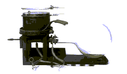
A simple cloud chamber consists of a few basic parts:
Chambers have what is called a sensitive area. This is an area just above the condenser that is sensitive to radioactive tracks. At this height, most of the alcohol has not yet condensed into clouds. This means that the ion trail left by the radioactive particles provides an optimal trigger for condensation and cloud formation. This sensitive area is increased in height by having a steep temperature gradient, little convection, and very stable conditions.
A strong electric field is often used to draw cloud tracks down to the sensitive region of the chamber. Typically around 100v/cm, it also serves to increase the sensitivity of the chamber. As radioactive particles pass above the sensitive area of the chamber, they too leave behind an ion trail.. The voltage in effect serves to draw these tracks down to the sensitive area of the chamber, where the condensation they cause can be seen. While tracks from sources can still be seen without a voltage supply, background tracks are very difficult to observe. In addition, the voltage can also serve to prevent large amounts of "rain" from obscuring the sensitive region of the chamber. This rain is caused by condensation forming above the sensitive area of the chamber. This means that ion trails left by radioactive particles are obscured by constant precipitation. The black background makes it easier to observe cloud tracks. When a white light illuminates the droplets from the side, they become very visible against the dark background.
If students have a hard time visualizing what is happening it can be convenient to use an example from everyday life. Often times airplanes pass high overhead on perfectly clear days. While it may be impossible to see the planes, often they can be seen by the contrails they leave. While the plane doesn't make these tracks by leaving an ion trial, the trail the plane leaves behind is still a cloud. Instead of the cloud being made up of alcohol droplets, it is made of water droplets. Thus, remembering the difference in physics, to visualize what is happening, we can think of the plane as being like a radioactive particle, and the sky as being like the cloud chamber. This type of chamber was originally used by T.R. Wilson around 1911 to study cloud formation. He also assumed than other radioactive particles would also leave cloud tracks in these chambers.
Condenser
The heart of our chamber consisted of a very large copper condenser plate, 1mm in thickness and 30 cm in diameter. Underneath this plate a long coil of 1/8" copper pipe was soldered. It should be noted that soldering a surface this large is reasonably time consuming (10 hours for an inexperienced solderer). Large plates like this act as large heat sinks. Because of this, one must be very aware or desoldering using even fine mouthed acetylene torches. This occurs very easily because of the good conductive properties of copper. To lessen this problem, as many clamps as possible should be used. Roughly 10m of pipe was used. The small diameter pipe was chosen so as to enable more contact with the condenser plate. This enabled a greater efficiency of nitrogen use. Due to the thin copper plate used, some warping occurred. This resulted in localized increase in cloud drift, which decreased as the chambers sensitive area of cloud formation rose.
The top of the copper was painted black with a standard rust paint. While most likely not suitable for a continuously operating cloud chamber, the surface proved to be surprisingly durable to the alcohol throughout many hours (~30+) of tests and operation. The bottom of the plate was insulated with a standard spray insulation. This proved to be very susceptible to alcohol attack.
Container
The sealed environment was constructed out of 1/2" Plexiglas due to availability and ease of construction. After time, the Plexiglas started to show signs of alcohol attack by the development of highly scratched areas. Glass, while requiring much more careful and perhaps professional assembly does not exhibit these ill effects. A 40cm x 40cm box was constructed that was 40cm high at one end and 30 cm high at the other, with a thin steel sheet serving as a base. This slope is only necessary if one intends to operate the chamber continuously as for a hall display. The corners of the base were bent to enable screws in the Plexiglas to hold the base. 20 cm from the roof, strips of Plexiglas were placed around the sides as a leveling strip and support for a copper cover sheet. The chamber was then screwed to a 24" x 24" x 12" wooden frame. The screws also held the leveling strip in place. One side of the chamber, small screws were placed into the Plexiglas to provide access. The door was split into two parts above and below the leveling strip. Two thin sheets of Plexiglas were also glued near the roof of the chamber perpendicular to the door. This provided a support for the voltage grid.
The copper cover sheet was used initially for aesthetic reasons to prevent views to the underside of the chamber. It did however prove to be a means to lessen draft current. The thin cover sheet was a 38.5 cm square with a 26 cm diameter hole cut out in the center. Around this edge was glued a soft rubber tube that sealed onto the condenser. Along the corners of the plate, holes were drilled for supports to the alcohol trough.
Alcohol Trough
In our chamber a 30cm x 30cm elevated trough was made for the alcohol. This chamber was constructed by taking two 3/8" copper pipes of 30cm and sawing them lengthwise in half with a hacksaw. Four copper corners were then used to join and solder the pipes together. The trough was supported by four 1/2" Plexiglas rods run through the cover sheet onto the steel base. Along the inside of the trough some highly resistive wire was used as an evaporator. The 4m of wire generated roughly 1 watt of power at 0.5 Amps. It was enclosed in a paper like insulator to prevent shortage to the copper trough. It should be noted that Langsdorf suggests that impurities caused by such things as a copper trough may impede chamber sensitivity. Plastic pipes may be a wiser alternative.
Voltage Grid
A 1/2" square galvanized mesh was placed along rails on the top of the chamber. This was connected to the positive terminal of a 3000 volt D.C generator. While not necessary if a source is used, the voltage serves to draw tracks that may have passed high in the chamber down to the sensitive region. Typically ~100 V/cm is a common figure.
Illumination
In order to see tracks, a simple fluorescent lamp was placed on the chamber's side. Illumination must come form the sides of the chamber. Overhead lights will only show the most obvious of tracks.
Cooling
Cooling was provided by pressurizing a large liquid nitrogen dewier with either an air hose. Two tubes were run through a rubber gasket held in place and screwed to the dewier by two aluminum plates.. As the dewier was pressured nitrogen was forced out and through the copper pipe under the condenser. Typically only a few litres of LN2 was required to cool down and run the chamber for an hour. The chamber could easily reach temperatures that would freeze the alcohol. Track formation could be seen from temperatures ranging from ~ -10 C to the freezing point of alcohol. Greatest sensitivity was attained when cooler temperatures could be stabilized for long periods of time.
Extra Tips For Use
Before tracks can be visible, a tangential light source is needed. This illuminates the white droplets against the black background. Drops should be viewed from as horizontal a position as possible. If the chamber is working correctly, tiny droplets should be seen condensing. Often this condensation is not apparent until a shallow pool of alcohol is formed at the condenser plate. For our use, the condenser was wetted with alcohol before use. This sped up the time until tracks were visible.
Tracks should be visible even without a large sweep voltage. Often tracks become much more obvious once temperatures and conditions have stabilized in the chamber. Once stabilized, the chamber is much more sensitive to background radiation. Stabilization also requires the elimination of any significant drift currents. These may occur due to poor chamber sealing. A simple silicon seal was placed on the chamber door as a gasket. Optimum temperatures for our chamber were around -50 degrees Celsius.
Cloud Chamber Demo
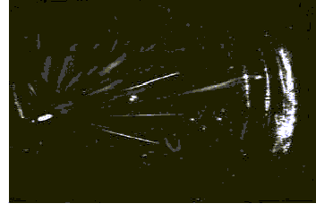
The main point of interest in the cloud chamber is the sight of radioactive tracks. Good chambers provide captivating viewing. Often students can sit at the chamber site for a large part of an hour, providing one can constantly pique their interest into what is truly happening. The tracks from radioactive alpha sources are easily visible. These tracks can be used to demonstrate the weak penetrating power of alpha particles. A simple tin sheet can be placed on one side of the source, and the disruption of tracks is obvious. While not done in this presentation, rough estimates as to the radioactivity of the source may be done.
More impressive to students are the tracks produced by background sources. Both the curling tracks of beta particles and the thick tracks of alpha particles can be observed. Many students are quite dismayed to have it pointed out that many of the tracks are directed directly at them. Explanations as to levels of background radiation are usually quite novel