Equipment
Overview
Pre-amplfier
Delay
Summing amplifier
Power supply
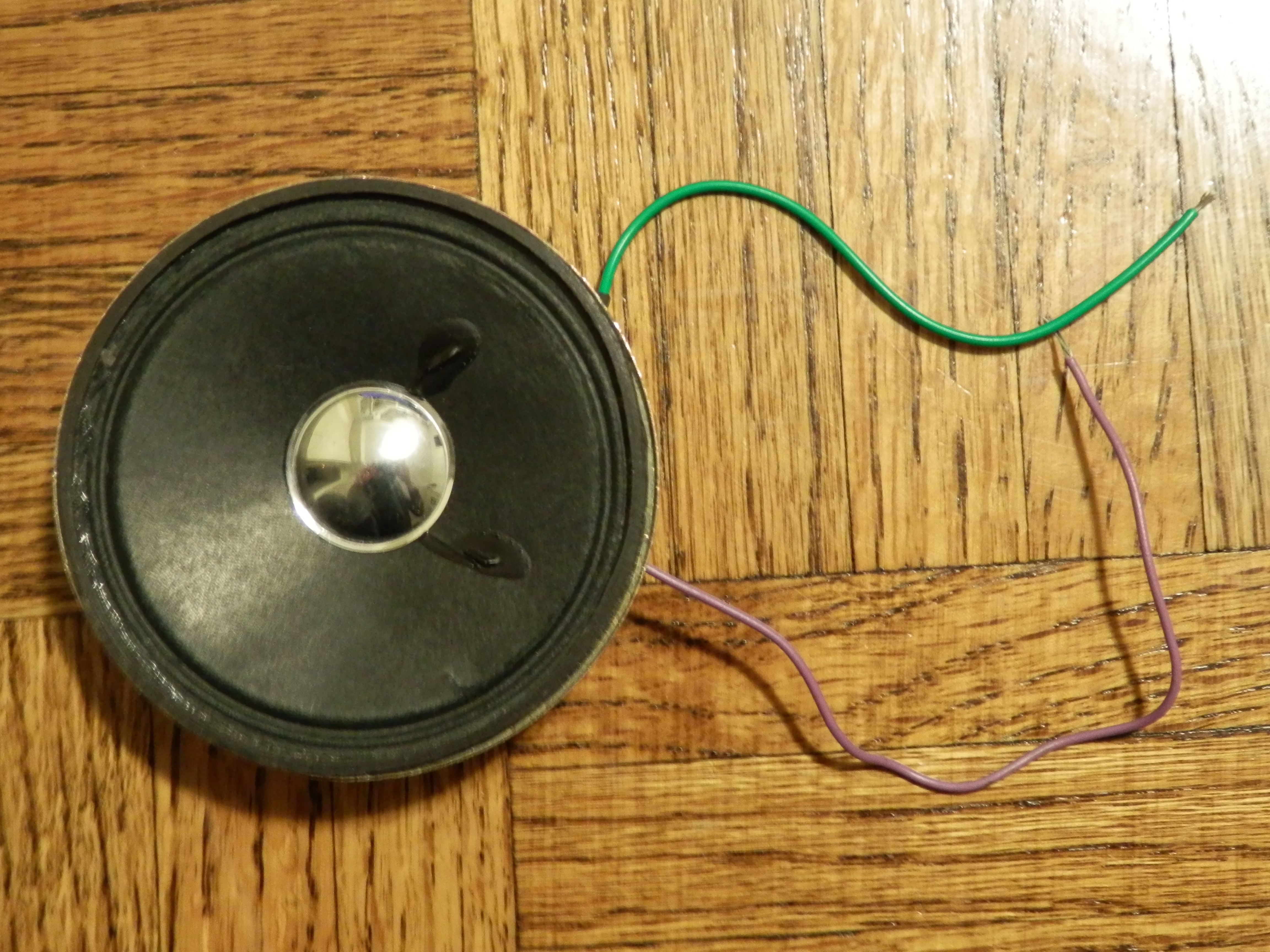
Speaker
Headphones
Using your new knowledge of how sound works and with a basic understanding of circuitry and electronics, you can construct an active noise-cancelling circuit (ANC)! This circuit can also be attached to headphone jacks to attach it to your heaphones!
The main idea behind noise-cancelling headphones involves the placement of a microphone on the exterior of the headphones, which picks up external noise. These sounds are then inverted (every sign is changed i.e. every positive value is now negative and every negative value is positive, amplitudes and the magnitude of the value itself does not change, only the sign) by a circuit and the new waveform is played through the headphone speakers together with the desired signal (music, voice/speech, etc). In theory, the signal and the inverted noise would cancel each other out (interference and superposition).
More complex noise-cancelling systems might also include microphones on the inside of the headphones to measure the amount of cancellation that is actually occurring. Some systems that are purely digital may also include adaptive filtering techniques which would greatly increase the precision and accuracy of the cancellation. Such systems are quite sophisticated and beyond the scope of this project (concepts such as filtering are not discussed on these webpages), which is of a primarily analogue design. The systems outlined on this page follow the basic principles previously discussed.
This method uses operational amplifiers (op-amps) (used as an amplifier, among other things), resistors (used to control the flow of electricity), and capacitors (used to store electrical energy).
Note that these are the bare minimum of requirements. Small changes in resistor size or capacitance may be needed if you find certain things are not working. Also, these are the requirements for one channel (if you are going for stereo), i.e. one ear if you decide to attach headphones. Double the requirements and build two circuits and you'll have a stereo system.
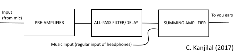
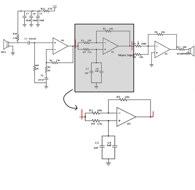
There are three main parts to this circuit: a pre-amplifier, a delay or all-pass filter, and a summing amplifier. If you owned a pair of noise-cancelling headphones, you might have (or might not have) noticed that there is likely a tiny hole on the external casing of each ear-piece. These are actually microphones. These are the microphones that are the input at the far left of the diagram above.
What happens is that the noise (an engine hum, for example) is picked up by the external microphones. This wave goes into the pre-amplifier, which amplifies the input wave by increasing the amplitude. This is one of the most basic uses of an op-amp. Think of it like a multiplicative factor and this factor is determined by the ratio of the two resistors.
The all-pass filter/delay does exactly what the name suggests: it delays the signal. But why? Recall that the speed of sound is about 340 m/s in dry air at room temperature. The speed of light is a universal constant is many orders of magnitude larger (~3 x 10⁸ m/s). Electrical signals travel at the speed of light. The time between the pre-amplifier and the summing amplifier is not negligible because of this difference in speed.
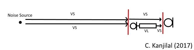
When the noise travels from the environment to your ear, it travels with the speed of sound. However, when the noise travels from the environment, then through the microphone and the rest of the circuit and then out the circuit to your ear, there is some time during which it travels at the speed of light, as illustrated in the picture below. So the delay works to line up the two signals.
Lastly, the summing amplifier does two things: it combines multiple signals using the principle of superposition and it also is another amplifier. This stage combines the music with the processed noise signal and then inverts the resultant wave.
Go to top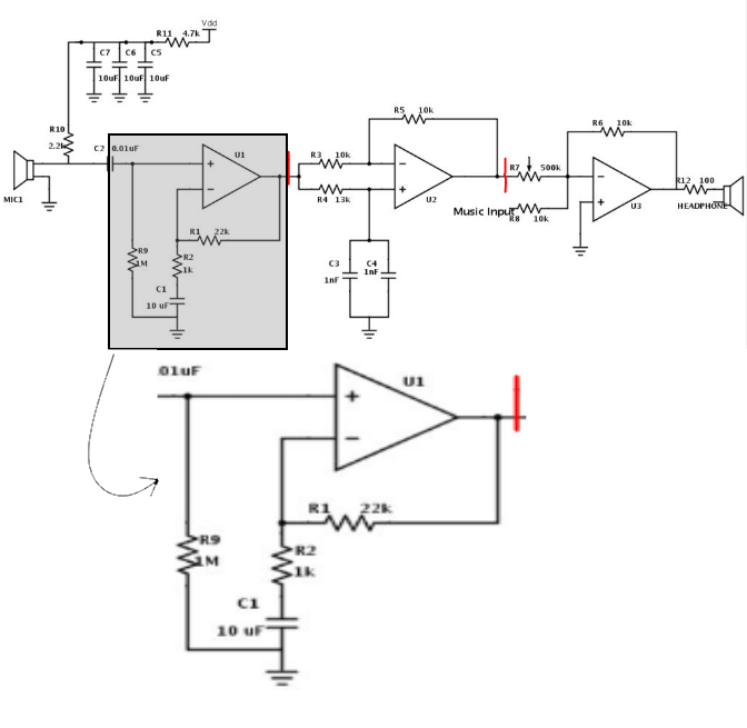
This next stage amplifies the noise signal to a higher level that can actually be processed (the waves themselves are tiny and would result in minute voltages which would be very difficult to deal with) and is a simple op-amp circuit that provides a gain to the incoming signal (see above). The gain of this op-amp circuit is simply the ratio of the resistances and the increase is approximately
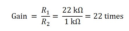 and an added bonus from this circuit is that it will also help to reduce any DC components and offsets that may appear, because DC offsets in the noise cancelling signal will cause issues that will compound as the signals travel through the circuit and will result in a poorly working system. From here the noise will pass to the delay.
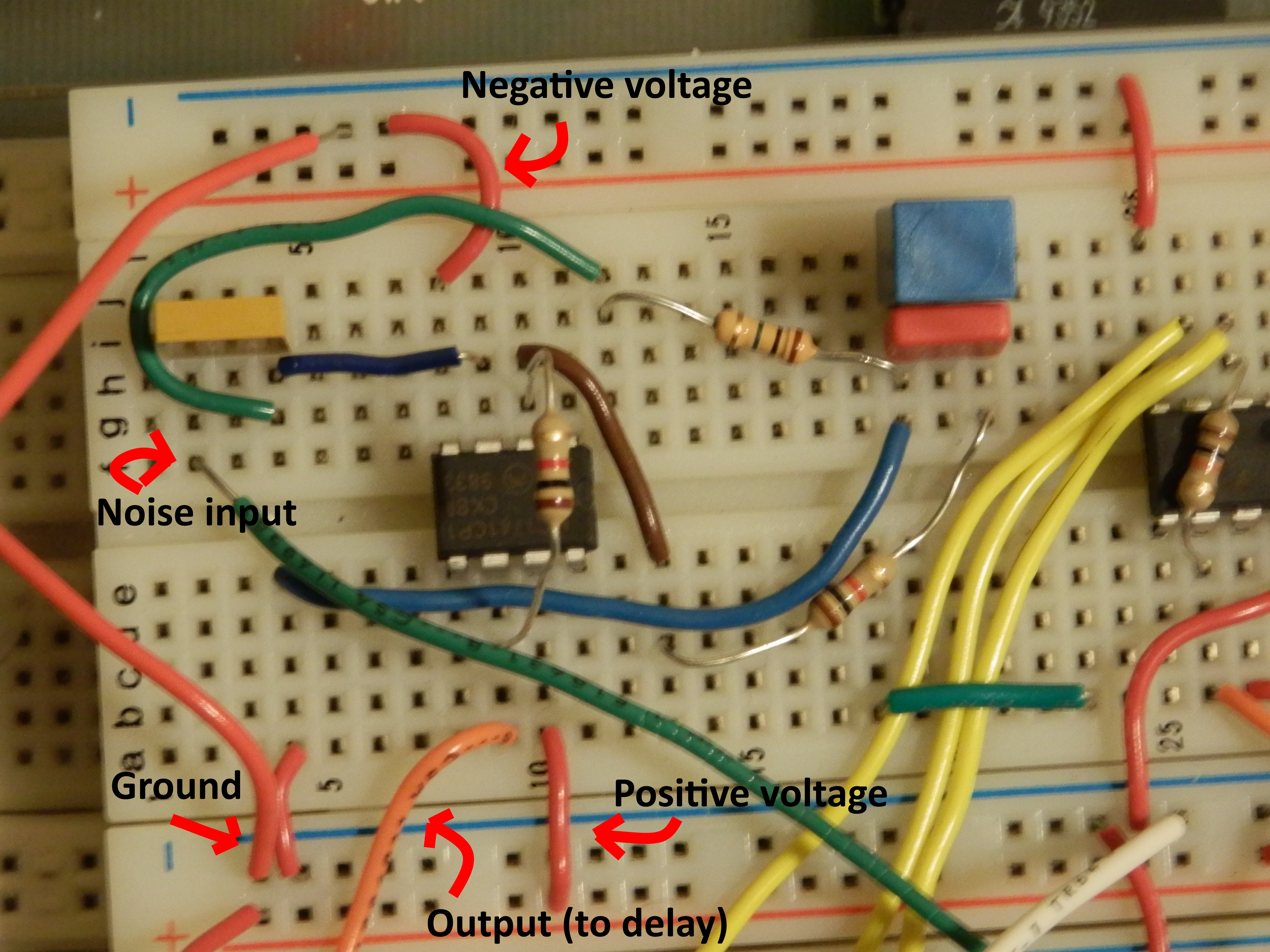
As mentioned earlier, the noise that is to be cancelled needs to be picked up by the external microphone and inverted and summed with other signals and this process takes time (which is not instantaneous or negligible). The all-pass filter provides the delay to the noise-cancelling signal that helps align all the signals and noise so that the summing process is much more effective. Recall that the noise from the environment is travelling at the speed of sound, which is much slower than the speed with which electric signals pass through the circuit. As a result of this, the noise from the environment actually will arrive an instant later than the inverted noise from the circuit to the ear and this will result in a weaker ANC. Below is the schematic for the delay.
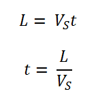
The problem of the delay adds some more items to consider when constructing the all-pass filter. In fact, the specific headphones that are used will have an impact on this portion of the circuit, should you choose to use headphones. If you do decide to use headphones, this next bit is important. Consider a pair of headphones where the distance from the external microphone to the ear itself is L. If the speed of sound is VS and the time delay is t, then the time delay can be calculated through some algebra (based on the equation for the speed of sound) as
This delay will likely be on the order of microseconds. The phase lag is then
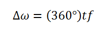
where Δω is the phase lag and f is the frequency of the sound. This frequency needs to be decided and is based on the range that the ANC is expected to perform. R4, C3, and C4 can be manipulated to work this out. The oscilloscope or the speaker may be very useful when working on this part.
Go to topThe last part of the circuit is outlined in the image below.
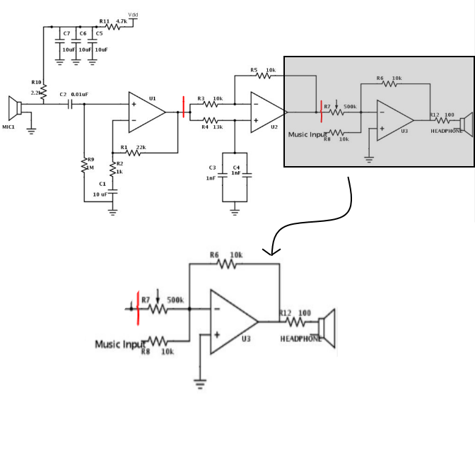
This last op-amp set-up combines the amplified noise with the music to form a superposition of the two. Then this sum of the waveforms is inverted. The most difficult portion here is that the amplitudes of all the signals and noise match properly. A potentiometer is used to aid this process. The gain of this primary component can be calculated as before. The input of the music will have no gain applied to it and the noise will have a gain of 0.02 times (see the figure below).

This may seem a bit confusing here because the latter is clearly not an amplification but the exact opposite. However, it will be called a gain for consistency. Perhaps the easiest way to make the amplitudes match is to manually test by adjusting the potentiometer until it sounds as if noise cancellation is taking place. Use the oscilloscope as well. Remember that all the resistances and capacitances provided are ballpark values and should be used as a guide. Make sure you are constantly checking with the oscilloscope and feel free to change some values as you see fit.
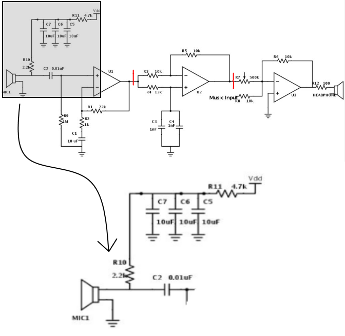
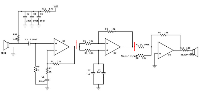
Although this is an optional step, it would be good to complete for a few reasons. The power supply filter, shown in the image above, is before the noise is passed to the first op-amp. In the schematic, C5-C7 and R11 act as a low-pass filter (i.e. attenuates higher frequencies but allows lower ones to go through) on the power supply (Vdd). This is important because high frequency noise may be present and it would be a benefit to have it removed from the microphone output otherwise something known as aliasing might occur, which happens when the circuitry has problems identifying the frequency of a signal. Aliasing causes distortions in the sound. Additionally, the resistor at R10 provides a bias (essentially a DC offset) if an electret microphone is used. The capacitor at C2 is used to remove the DC offset afterwards and only allow the noise that the microphone detects to pass. The output from the capacitor then leads to the first primary component: the pre-amplifier.
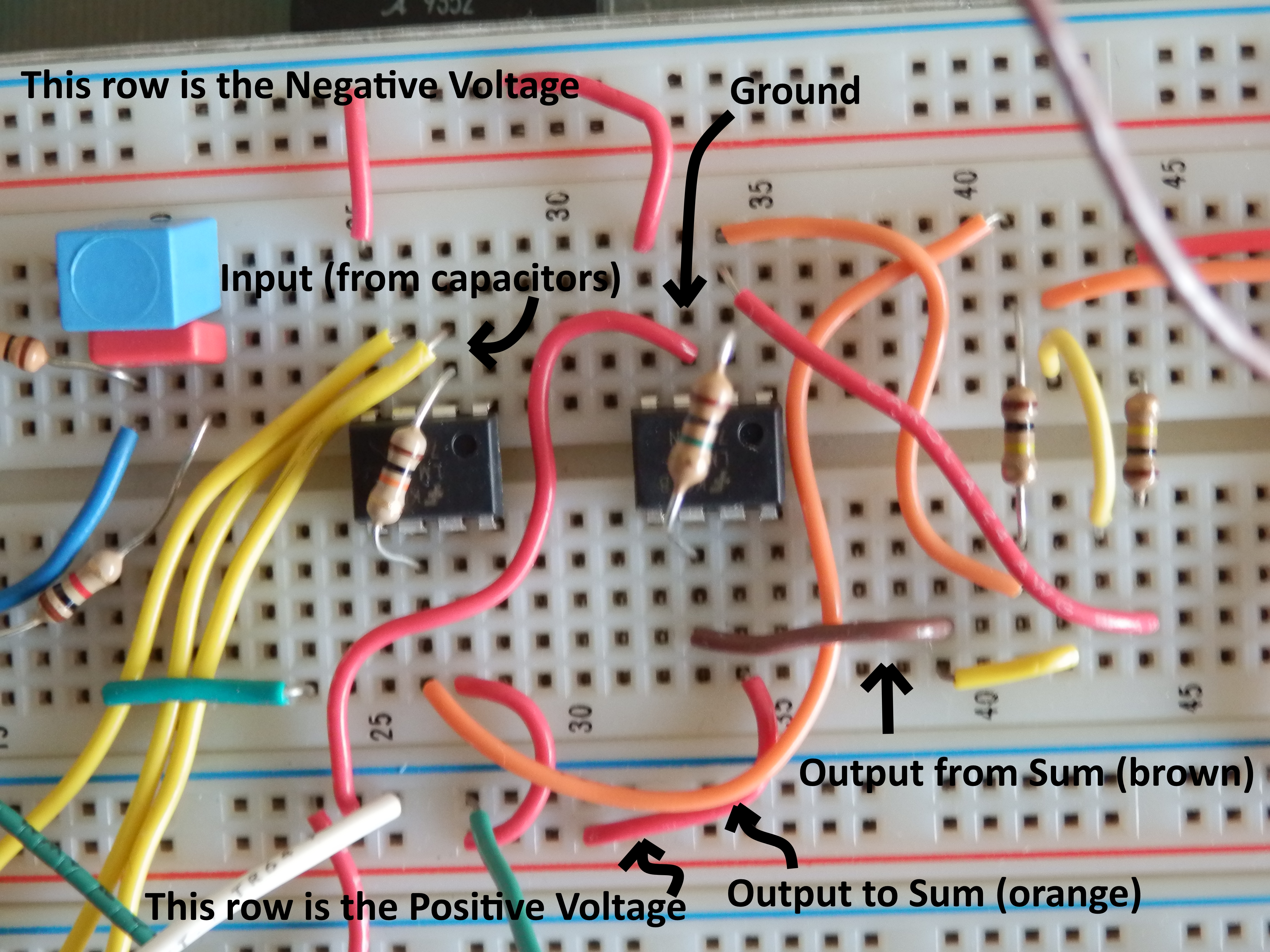
Go to topIf you choose not to add headphones, you can still observe and hear the noise-cancelling effects with a speaker. This is a simple addition, instead of adding the headphones to the circuit (see below), simply send the output of the summing amplifier to a speaker.
One wire of the speaker will either need to be connected to the ground or to a small power source (~5 V, usually, for small speakers). You may also consider adding a second summing amplifier to imitate what is going on in the ear. This second summing amplifier should take the first summed wave (noise and music) and combine it with the uninverted noise to imitate the cancellling. Then if the speaker is placed here, one can hear the effects. Experiment with placing the speaker at various parts of the circuit. For example, use it to hear the amplification of the pre-amplifier, use it to listen to the noise from the microphone, or use it to hear the effects of superposition in the summing amplifier. The speaker is a nice tool for these observations.
This final stage depends on the headphones that are being used. Headphones have an inherent impedance, essentially a resistance, associated with them (check the specifications of your pair). Ohm's Law describes the relationship between resistance, voltage, and current. However, this only works in the case of direct current (DC). The alternating current (AC) analogue is
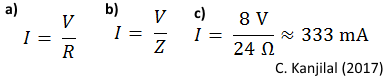
Since the initial power supply needs to be at least ±8 V, and if the headphone impedance is 24 Ω (a typical amount for lower end headphones), then the figure above describes that the maximum current is about 333 mA. It is likely that this will be a much greater current than is safe for the headphones. The resistance at R12 can be added and modified to limit this current to a value that is safe for the headphones. A lower current will also protect the ears (as essentially the more current, the higher the volume).
Now that the circuit is complete, the last thing to do is to attach the external microphones to the exterior of the heaphones and perform more tests (you should be testing all along the way to make sure thing are working as they should, make sure you understand and see what is happening at each major section). Congratulations! Your circuit should be up and running now!
Go to top