The Pitch-Control Theremin
A circuitry and electromagnetism demonstration.
By Kara Deane for UBC PHYS 420, 2021-2022.
Overview
The theremin is a unqiue instrument that creates music by controlling the capacitance in circuits. As such, the theremin can be used to demonstrate various physics principles related to circuitry and electricity and magnetism.
This webpage documents the design, construction, and presentation of a theremin demonstration and lesson intended for a Physics 12 audience.
Please be careful with the volume of the videos throughout this webpage - the volume setting can be quite loud and some of the videos have high-pitch sounds.
Physics Concepts
The concepts illustrated by this theremin demonstration and lesson are likely to be a bit beyond the Physics 12 curriculum. However, they do relate to concepts learned throughout the BC Physics 11 and Physics 12 curriculum, as well as concepts that Physics 12 students might have experience with through classes like Engineering and Electronics. The concepts are described in more detail in the presentation slides, available here and in the "Presentation" section. The primary concepts are as follows:
- Current in circuits can oscillate
- An oscillating circuit can be made using inverters and capacitors
- Modifying the capacitance in such a circuit controls its frequency
- Circuits can produce an electric field around an antenna
- An antenna can act as a capacitor plate and a person's hand can act as another capacitor plate
- Waves oscillating at similar frequencies can be combined to create a lower frequency wave, called "beats"
- The current from an oscillating circuit can be sent through a speaker to produce a sound wave
Design
The theremin demonstration consists of two circuits: a simple oscillating circuit, and a complete theremin circuit. The materials list for the entire demonstration can be found here (open materials list in new tab). Note that if the exact values of capacitors or resistors are not available, you can combine other values to get the desired value.
The design for the complete theremin circuit was informed by the website "Art's Theremin Page". This is an excellent resource for learning more about theremins and seeing some alternative designs. Visit Art's Theremin Page.
Simple Oscillating Circuit
The simple oscillating circuit is a type of circuit called an "RC Oscillator". It uses a capacitor, resistors, and inverters to create a feedback loop that produces a square wave. The frequency of the square wave depends on the value of the resistance and capacitance in the circuit. This type of circuit is a main component of the theremin, so it is pedagogically beneficial to discuss it as a discrete module. Below is a circuit diagram and components list.
| Label | Type | Value |
|---|---|---|
| R1 | resistor | 270 kOhms |
| R2 | resistor | 27 kOhms |
| C1 | capacitor | 100 pF |
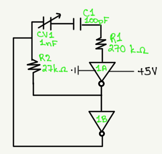
| CV1 | variable capacitor | 1 nF |
| 1A | hex inverter: CMOS CD4069UBE | N/A |
| 1B | hex inverter: CMOS CD4069UBE | N/A |
The value of the resistors and capacitors here is not critical. However, it may be useful to use similar values to those that are in the theremin circuit so the square wave output is similar to what will be seen in the theremin.
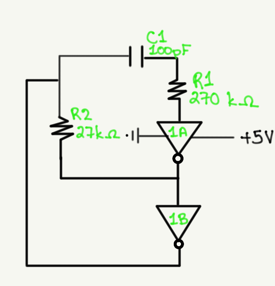
For the first part of the demo, the capacitance is fixed according to the circuit shown above. For the second part of the demo, a variable capacitor is added in series next to the 100 pF capacitor according to the circuit shown below. This is to show how varying capacitance varies the frequency of the output square wave (see more about demo steps in the "Presentation" section).
Complete Theremin Circuit
The theremin circuit consists of four connected modules: two RC oscillators, one mixer, and one amplifier. One of the RC oscillators produces a square wave with a fixed frequency. The other RC oscillator produces a square wave with a variable frequency, as the capacitance in this RC oscillator can be varied. The mixer combines the square waves from the two RC oscillators into a single wave with a lower frequency, known as a beats wave. The frequency of this wave is what determines the pitch of the sound wave being output by the theremin and depends on the frequency of the two waves that were combined to create it. The amplifier increases the amplitude (voltage) of the wave from the mixer and sends it to a speaker which produces a sound wave. More information on how these modules work can be found in the presentation slides, linked in the "Presentation" section. The design of each of the four modules and the overall complete circuit is described below.
RC Oscillator (fixed frequency):
The fixed frequency RC oscillator is nearly the same circuit as the RC oscillator previously described. There are some additional components controlling the power supply to the ciruit.
| Label | Type | Value |
|---|---|---|
| RV1 | variable resistor | 10 kOhms |
| RV2 | variable resistor | 1 kOhm |
| R3 | resistor | 22 kOhms |
| R4 | resistor | 270 kOhms |
| R5 | resistor | 27 kOhms |
| R6 | resistor | 27 kOhms |
| C2 | capactior | 100 pF |
| C3 | capacitor | 10 uF |
| CR2 | diode | N/A |
| 1A, 1B, 1C | hex inverter: CMOS CD4069UBE | N/A |
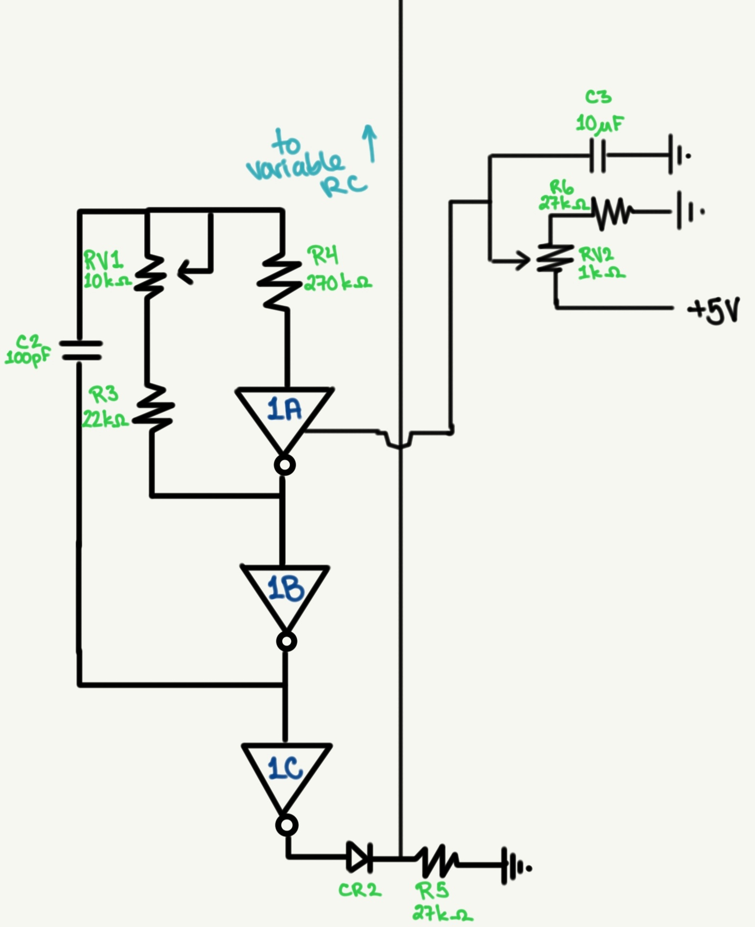
The resistance in the circuit is made up of fixed and variable resistors. The variable resistors can be manipulated to tune the theremin but are not altered while playing it. As before, 1A, 1B, and 1C are each gates on a hex inverter.
RC Oscillator (variable frequency):
The variable RC oscillator is again quite similar to the previously described RC oscillators, but is attached to an antenna. The antenna acts like one half of a parallel plate capacitor, and the player's hand acts like the other half. Thus, by varying the distance between the antenna and player's hand, the capacitance in the circuit can be varied. In this manner, the frequency of the circuit's output square wave can be varied.
| Label | Type | Value |
|---|---|---|
| R1 | resistor | 270 kOhms |
| R2 | resistor | 27 kOhm |
| C1 | capacitor | 100 pF |
| CR1 | diode | N/A |
| 2A, 2B, 2C | hex inverter: CMOS CD4069UBE | N/A |
| Antenna | metal plate | approximate area = 0.13 m^2 |
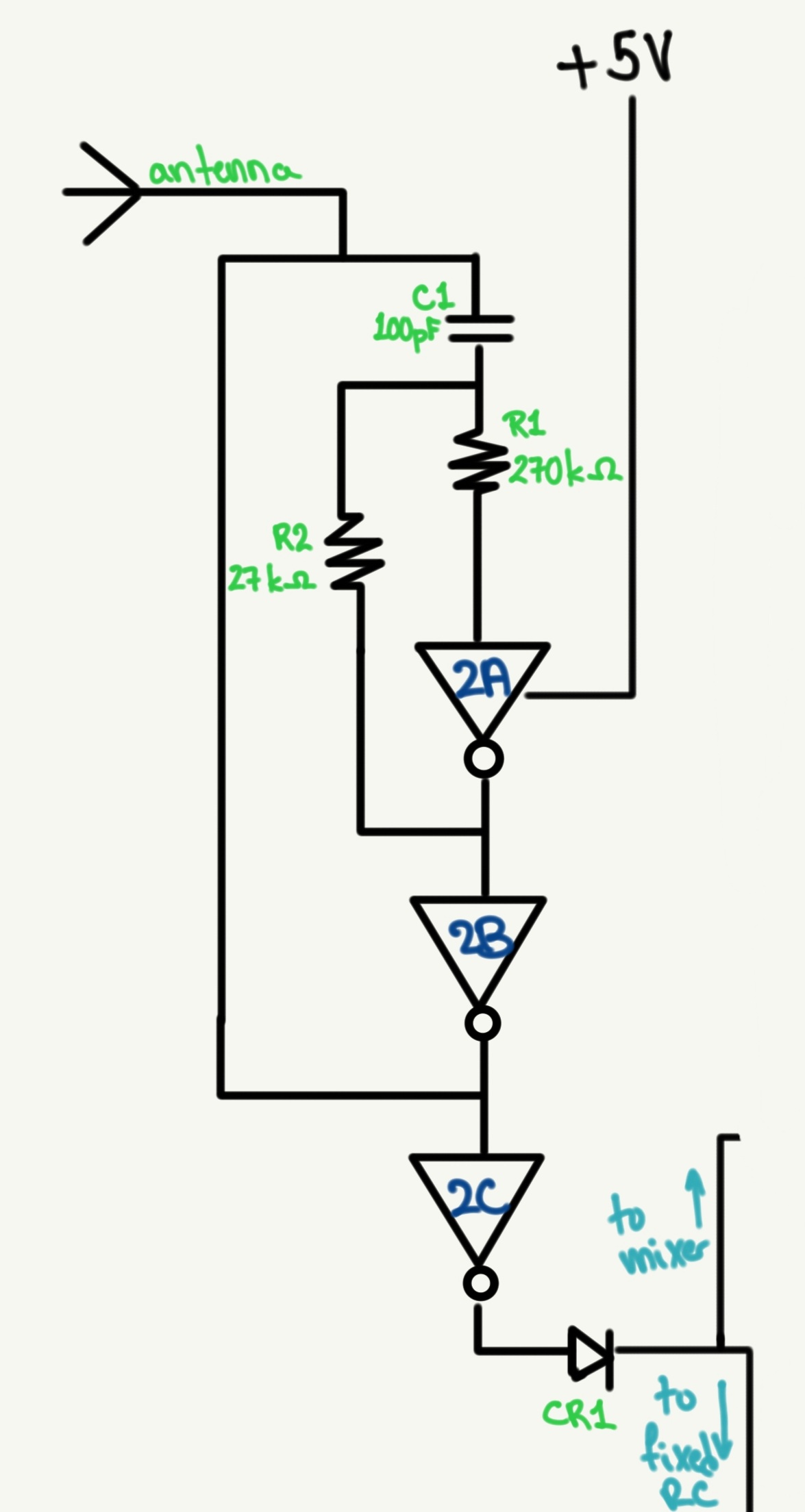
The shape of the antenna is not critical. The recommended area is approximate, but your plate should have a similar area. I used a circular metal plate about 0.5 cm thick with a diameter of 20 cm.
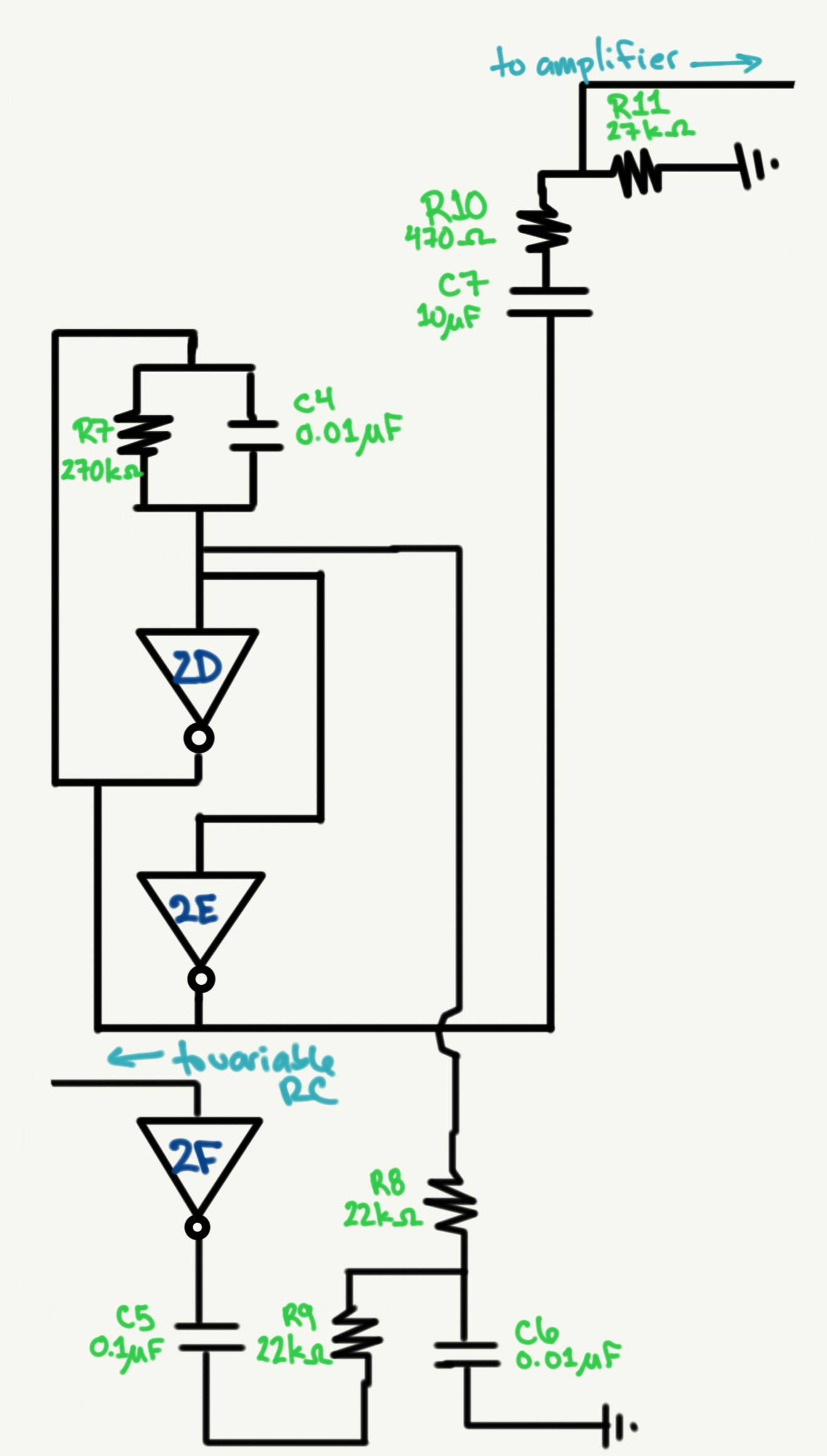
Mixer:
The mixer creates a beats wave from the two RC oscillators. The frequency of this wave is affected by small differences in the frequencies of the square waves coming from the RC oscillators. The frequency of the wave output from the mixer corresponds to the pitch of the sound wave produced. The circuitry for the mixer is not explored in detail in the demonstration and presentation.
| Label | Type | Value |
|---|---|---|
| R7 | resistor | 270 kOhms |
| R8 | resistor | 22 kOhm |
| R9 | resistor | 22 kOhms |
| R10 | resistor | 470 kOhm |
| R11 | resistor | 27 kOhms |
| C4 | capacitor | 0.01 uF |
| C5 | capacitor | 0.1 uF |
| C6 | capacitor | 0.01 uF |
| C7 | capacitor | 10 uF |
| 2D, 2E, 2F | hex inverter: CMOS CD4069UBE | N/A |
Amplifier:
The design for the amplifier is up to the individual. I used a very simple amplifier circuit that worked for the circuit components I already had. There are many such designs available online, and the theremin circuit can also be connected to a pre-made amplfier or active speakers via audio jack. That being said, my amplifier design is detailed below, as based on an amplifier design from circuitbasics.com.
| Label | Type | Value |
|---|---|---|
| RV3 | variable resistor | 10 kOhms |
| R12 | resistor | 10 Ohm |
| C8 | capacitor | 0.1 uF |
| C9 | capacitor | 1000 uF |
| switch | slide switch SS22D18 | N/A |
| speaker | breadboard mount | 0.2 W, 8 Ohm |
| 3 | integrated circuit: LM386 audio amp | N/A |
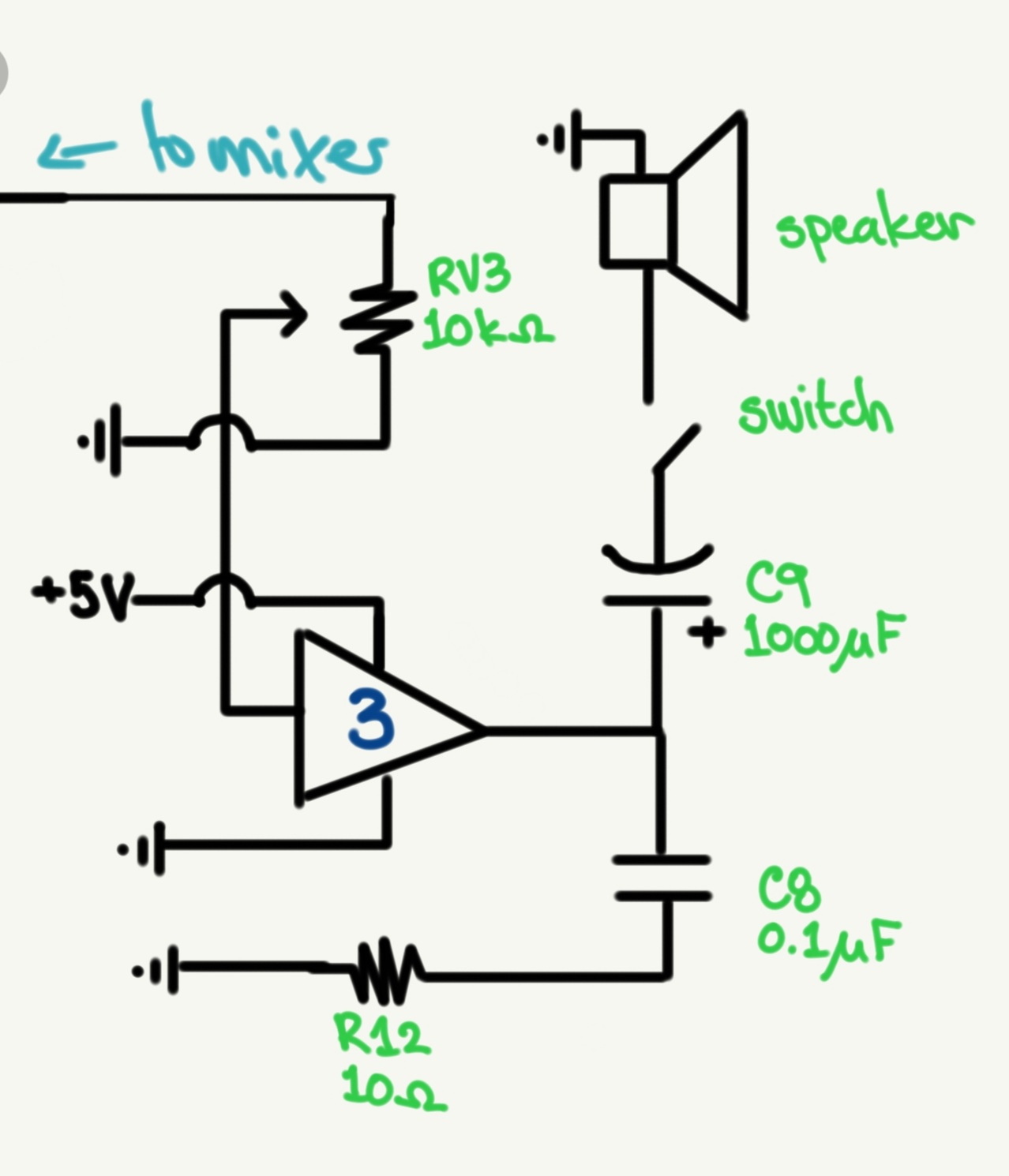
The LM386 audio amp is very common in simple amplifier circuits. I used the listed switch and speaker because they were most accessible to me, but using other types may also work. Be sure to select a speaker which can be powered appropriately by the circuit. Most capacitors with a value of 1000uF have a specific polarity, so be aware of that when choosing a capacitor and putting it into your circuit.
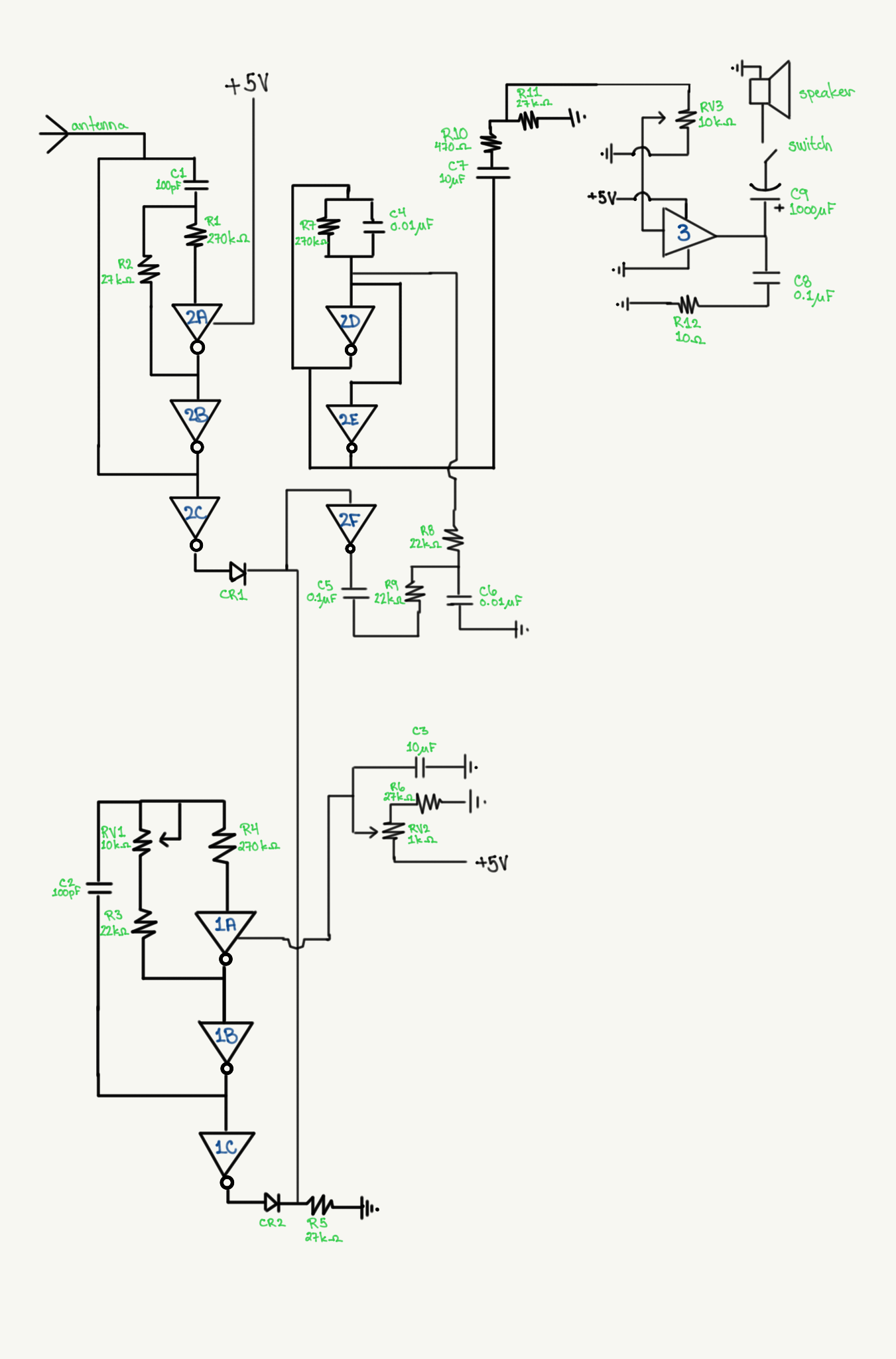
Complete circuit:
The complete circuit diagram for the theremin with connections between modules is shown below. Open as PDF here.
Construction
Once you are comfortable with the circuit designs, construction is very straightforward.
I recommend building one module at a time and ensuring it is working correctly before starting on the next. As you go, make sure that your power supply is connected correctly and that the voltage to which you are connecting components (especially integrated circuits) is appropriate. Datasheets for integrated circuits are linked as PDFs throughout the "Construction" section, and data sheets for the integrated circuits and other components are also available online. The data sheets will give you information on how to connect components and what their safe operating ranges are. "Ground" for the circuit is connections to the ground pin of the power supply. You can use the oscilloscope to help debug the circuit as you are building it. It can be helpful to take pictures before you make changes to your circuit so you can return to a previous iteration easily.
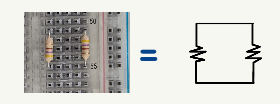
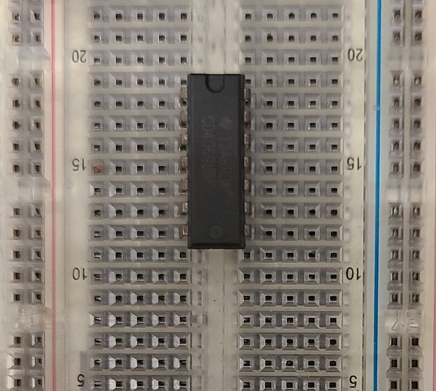
The circuit components are connected via wires or via the strips of conductive solder running between the ports on the breadboard. The solder connects ports across the width of the breadboard but not along the length of the breadboard. The exception is the power and ground rails marked with blue and red on the side of the breadboard. Connections along these rails are soldered length-wise and not width-wise. The power and ground rails are not connected to the other ports. See the picture below for an example illustrating how the breadboard ports are connected.
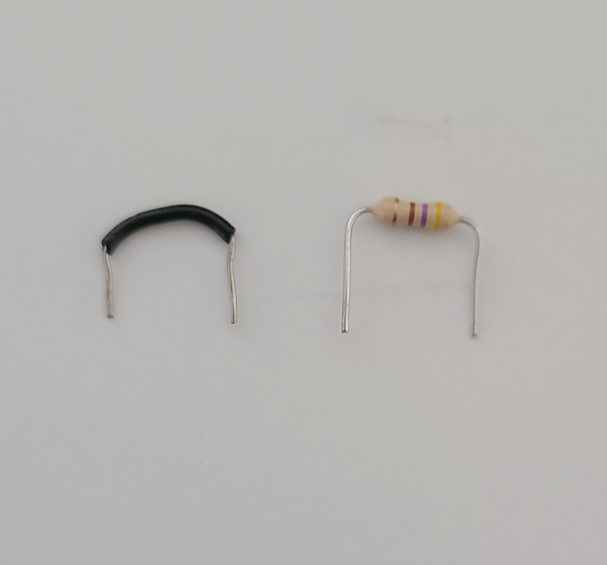
When connections are made with wires, the wire should be kept short to reduce impedance and facilitate debugging. Use wire strippers to remove enough of the insulation to ensure a good connection between the wire and the breadboard port. The leads coming off of components like capacitors and resistors should be gently bent in to shape and gently pushed straight down into the breadboard. Excess wire for leads can be trimmed away. See the picture below for an example of my preferred lead length.
We will now go through the construction of each module using the same approach as we did for the design.
Simple Oscillating Circuit
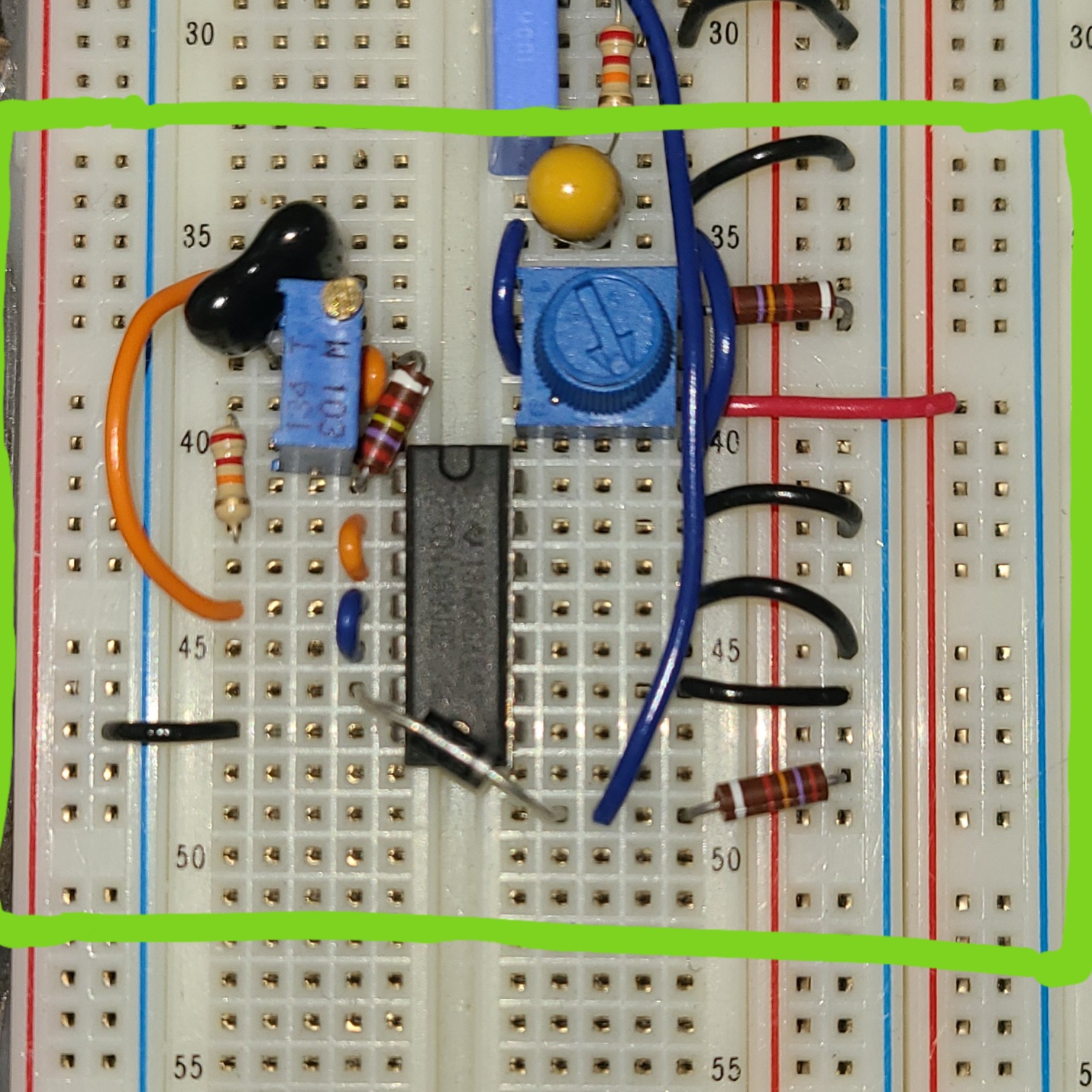
I used a separate breadboard and power supply for this circuit so it was a bit easier to use during the presentation. You could in theory put this smaller circuit on to the same breadboard as the theremin, but you want to ensure it is separate enough that it doesn't get coupled with the theremin circuit and can easily be seen during the demo. To construct this circuit, simply attach the circuit components as shown in the circuit diagrams. Note that inverters 1A and 1B are two gates on a single hex inverter chip. The VCC pin for the hex inverter should be connected to +5V from the power supply, while the ground pin and any unused input pins should be attached to ground (click to open datahseet for hex inverter as a PDF). The images below depict the circuit diagrams and constructed circuits with and without the variable capacitor.

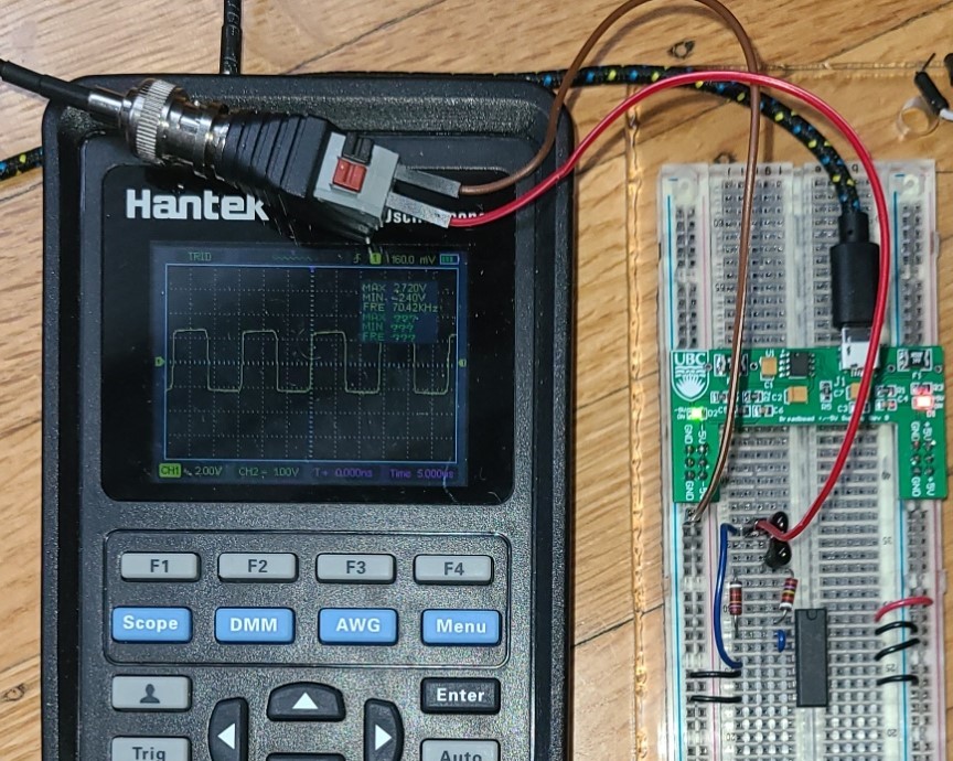
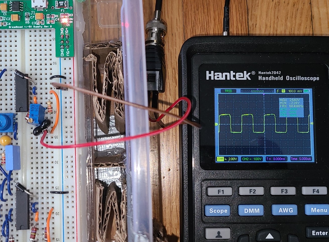
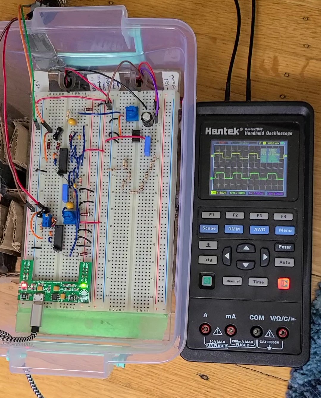
You can connect the oscilloscope between the capacitor and the input to 1B on the hex inverter, as shown in the image below. The expected frequency is around 70 kHz with just the fixed capacitor. When you put in the variable capacitor, the frequency reading should change as you change the capacitance (see the video below). The output on the oscilloscope should be a square wave.
Fixed RC oscillator:
The fixed RC oscillator uses 3 sets of input/outputs on one hex inverter. The hex inverter's ground pin should be connected to ground, as should the unused input pins (open datahseet as PDF here). The arrows pointing to RV1 and RV2 in the circuit diagram indicate the "wiper", which should be connected as indicated in the circuit diagram and data sheet for your specific components. RV1 and RV2 don't need to be set to a specific value yet, they will be set when the theremin is tuned. R5, RV2, and C3 are all connected to ground. RV2 should be connected to +5V from the power supply, and the hex inverter should be powered from between C3 and the wiper for RV2. CR2 is a diode which needs to be connected in the correct direction. See the data sheet for your specific components for more information.
The oscilloscope can be connected between C2 and the input to 1C as shown in the image below. The output should be a square wave with a frequency of between 60-75 kHz. The frequency can be set by RV1 during tuning.
Variable RC oscillator:
The variable RC oscillator uses 3 sets of input/outputs on a new hex inverter. The hex inverter should be powered from the +5V supply, and the ground pin and unused input pins should be connected to ground (open datahseet as PDF here). CR1 is a diode which needs to be connected in the correct direction, see the data sheet for your specific component for more information. The connection after CR2 goes to both the mixer and the fixed RC oscillator modules. The antenna is connected by a wire between C1 and the input to 2C (the black wire connected between the black capacitor and the orange wire). At this stage, you can use a stand for the antenna plate or just place the plate 8-10 inches away from the circuit and build the stand later. The wire I used to connect the antenna was about 12 inches long and connected to the antenna with electrical tape. Use a fairly long piece of wire so that you can cut it down to the correct size when you add the antenna stand. More information about the antenna set-up can be found in the following "Complete Theremin" section.
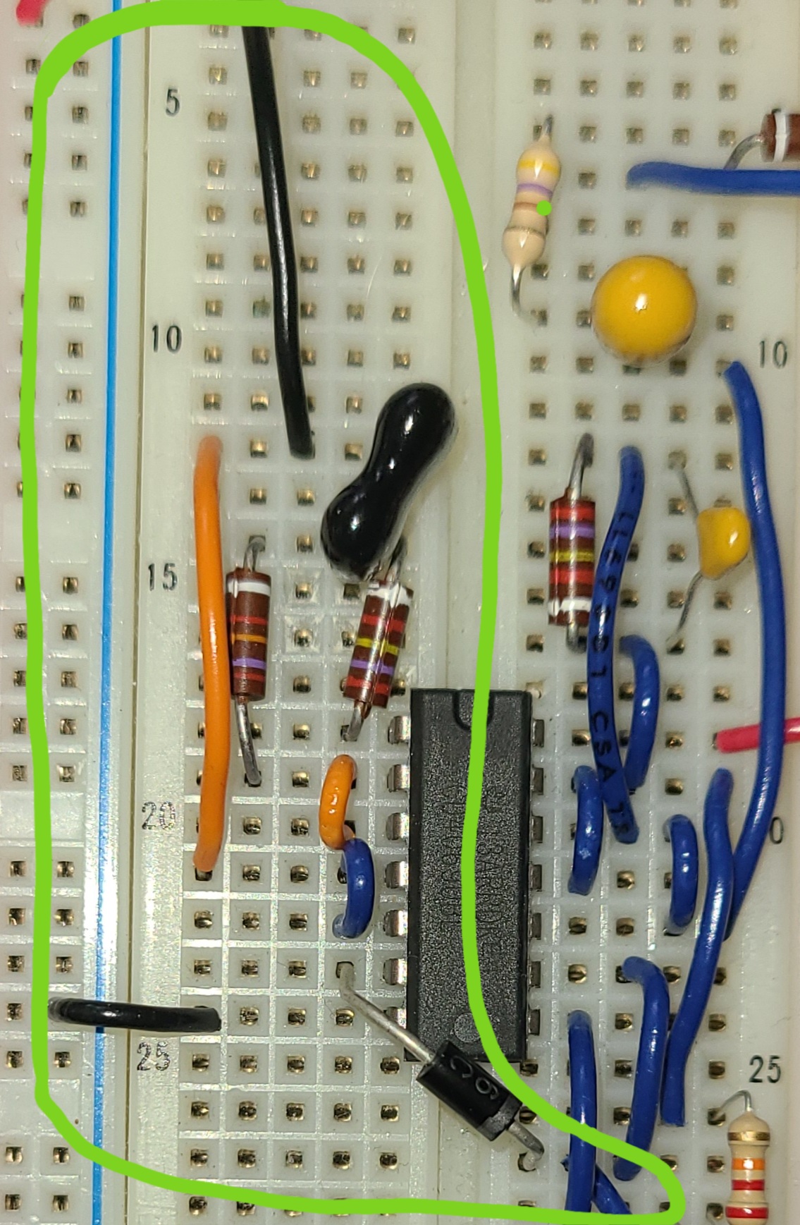
The oscilloscope can be connected between the antenna and the input to 2C as shown in the image below. The output should be a square wave with a frequency of around 60-75 kHz. The frequency may vary a bit depending on the area of your antenna plate.
Mixer:
I used the remaining inputs/outputs from the hex inverter used in the variable RC oscillator for the mixer. The hex inverter is already grounded and powered from the construction of the variable RC oscillator module. C6 and R11 are connected to ground, and R7 and C4 are connected in parallel.
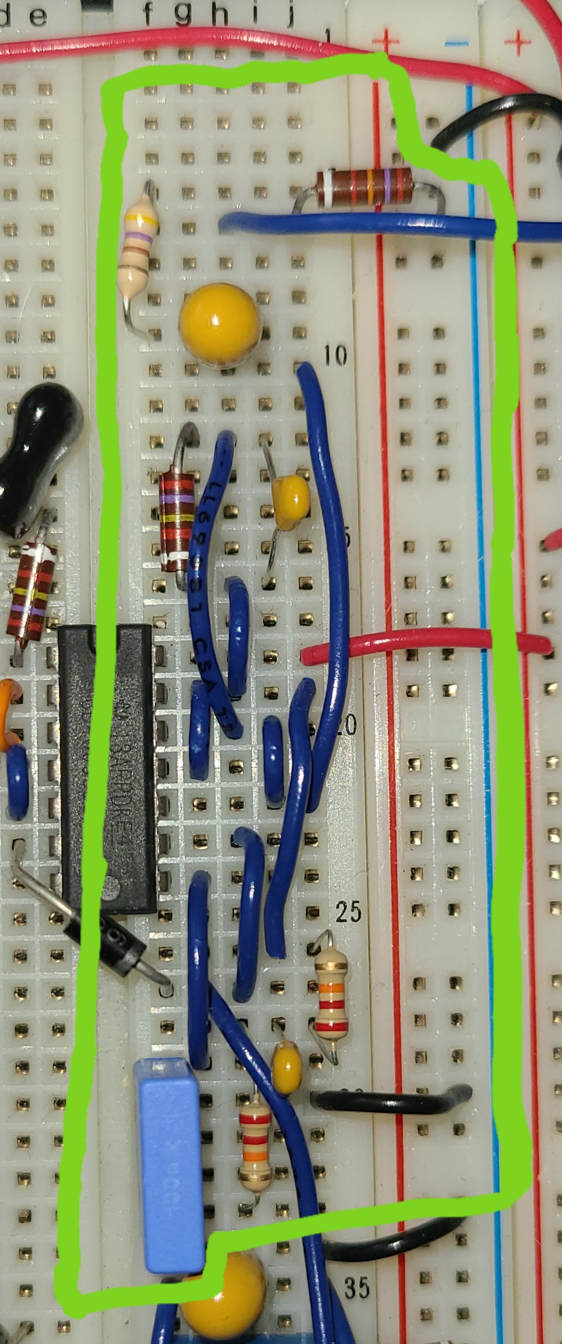
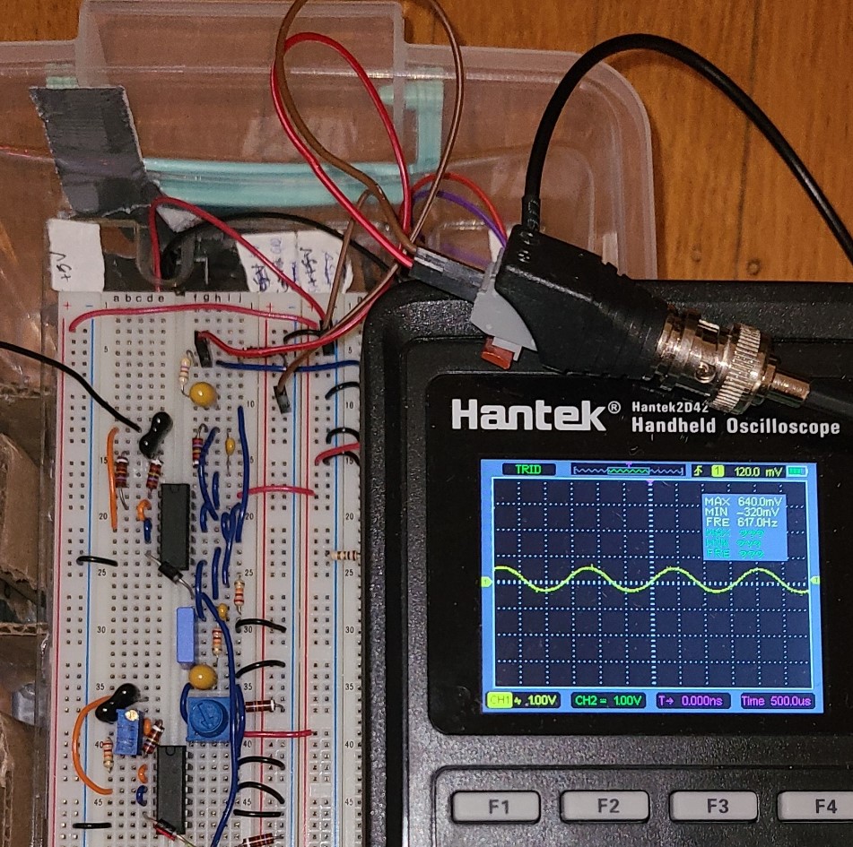
The oscilloscope can be connected between R10 and R11 as the image below shows. The frequency output from the mixer should be much lower than from the RC oscillators. For my circuit, the RC oscillators' output was around 70 kHz and the mixer's output was around 300 Hz. The wave is also smoothed from a square wave to a sine wave in the mixer.
Amplifier:
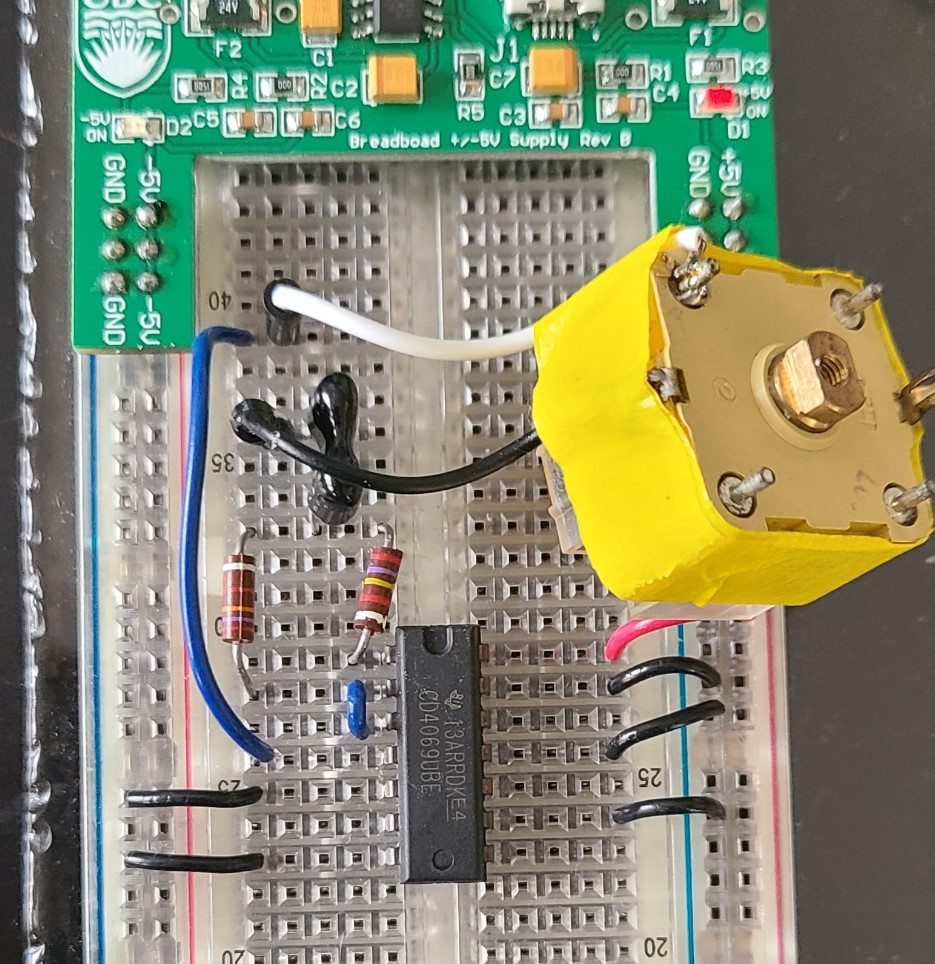
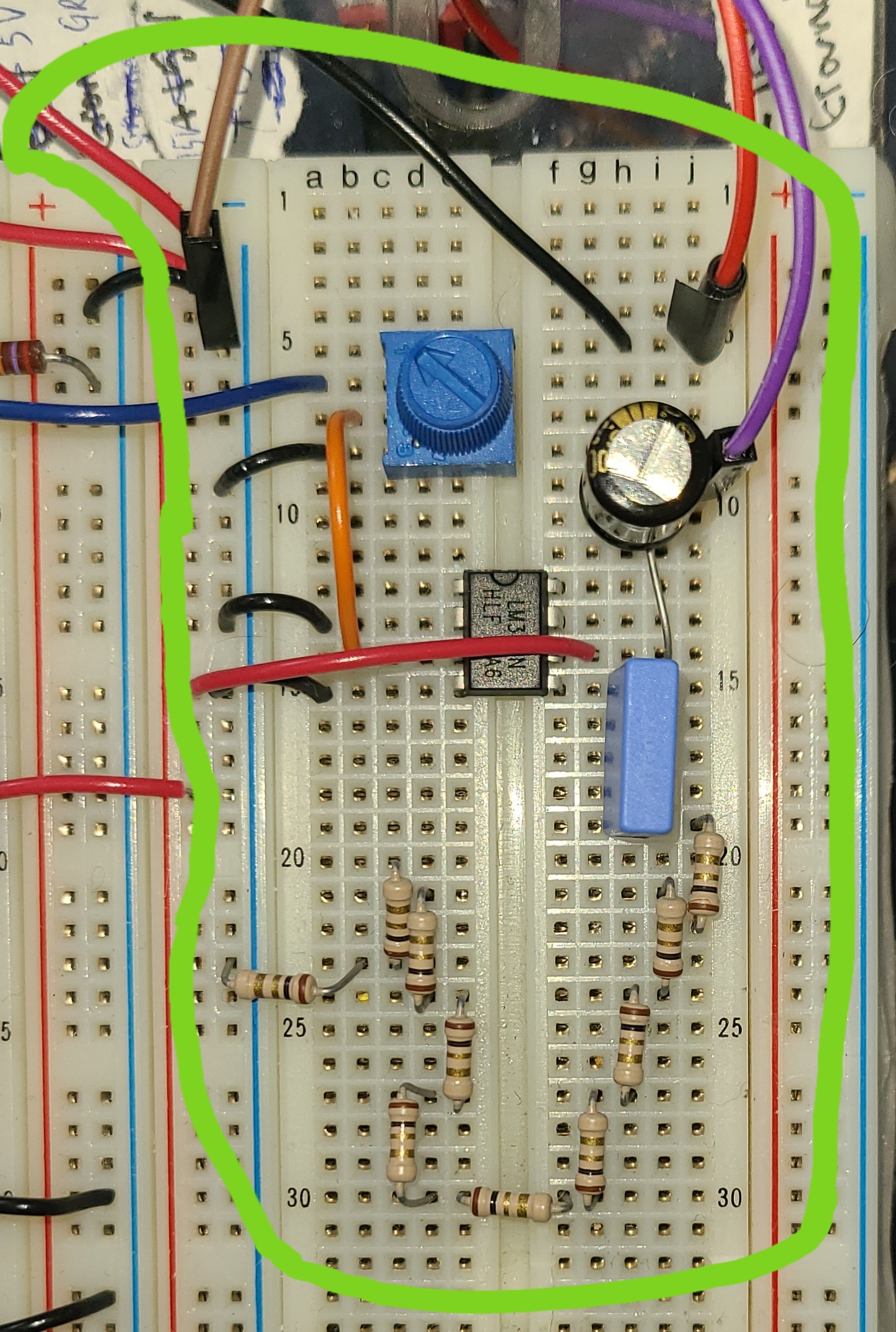
The amplifier uses a dedicated integrated circuit, the LM386 op amp. This integrated circuit can be connected to +5V from the power supply and grounded as indicated in its datasheet (PDF available here). I put a connection across from the power and ground rail on the other side of the breadboard so that I had easier access to a power and ground rail. RV3 is connected to the mixer and to ground, with its wiper going to the appropriate connection in the op amp according to the datasheet. After tuning the theremin, you can adjust RV3 to an appropriate volume level. R12 is connected to ground. Because C9 has a higher value, it is likely to be polarized and should have the + side toward the op amp output. The switch allows the signal to get to the speaker, so the theremin will be silent with the switch open. To test the mixer and amplifier output with the oscilloscope, make sure the switch is closed so the circuit is complete through the speaker. You can see in the picture below that I didn't have a 10 Ohm resistor for R12, so I combined 10 x 1 Ohm resistors to get the correct value.
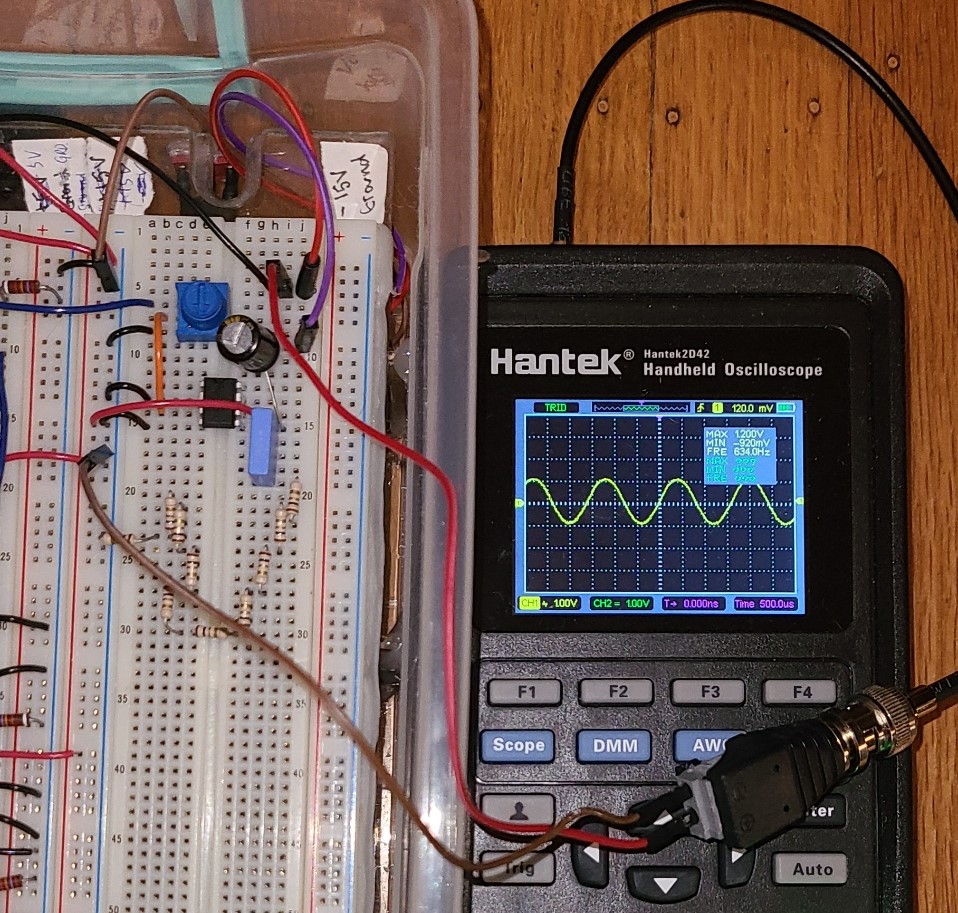
To debug the amplifier, you can connect the oscilloscope between C9 and the speaker (I connected it between the switch and speaker because that side of the switch was easier to access in my layout). The amplitude (min to max voltage on oscilloscope) should be greater than what was output by the mixer, but the frequency should be about the same. The frequency of the mixer and amplifier output will noticeably change with proximity of yourself or other objects to the antenna.
In the circuit picture, the purple jumper wire leads to the switch's input, the brown jumper wire leads to the switch's ground, and the red jumper wire leads to the switch's output. The black wire next to the red jumper leads to the speakers' input, and the red wire next to the brown jumper is ground for the speaker. The speaker and switch are mounted on the side of the casing as shown below.
Complete theremin:
Make the remaining connections between the modules as indicated in the circuit diagram (open as PDF here). You should have a circuit which looks something like the picture below. I removed my connections to the switch and speaker to take this picture as they are mounted in my casing.
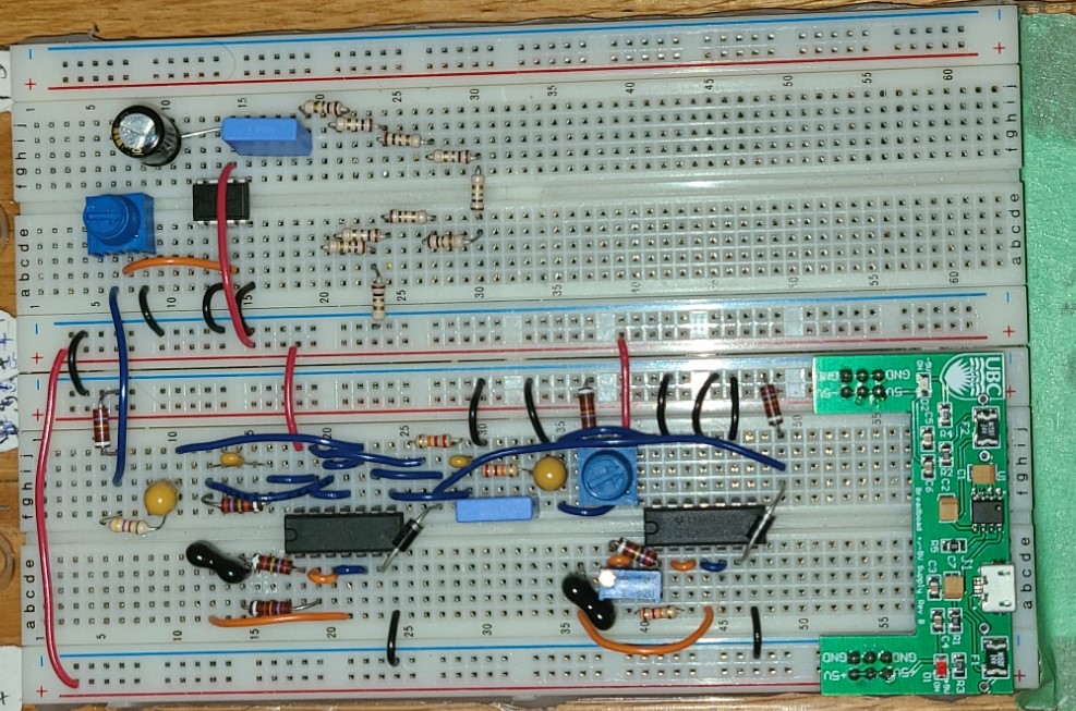
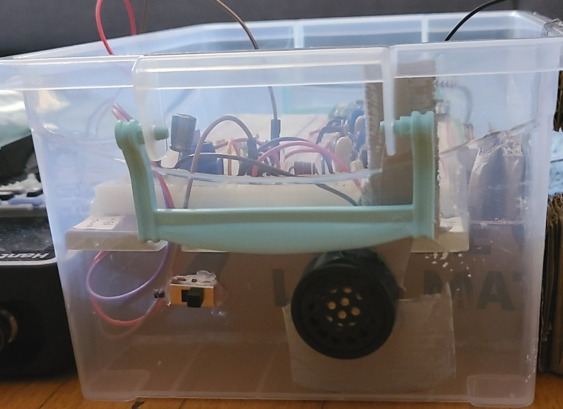
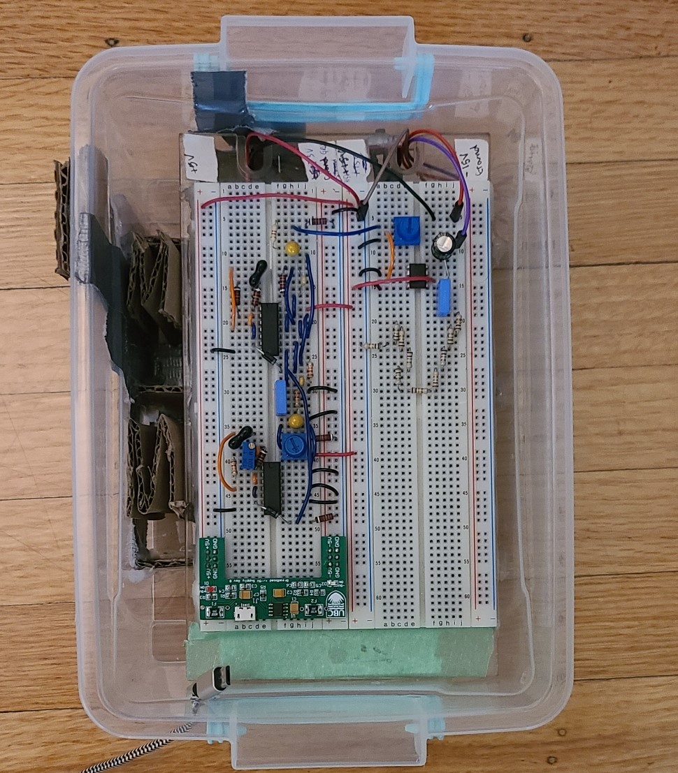
It is not critical that the following steps regarding the casing and antenna stand are completed the same way I did. Essentially, you want a secure case to protect the theremin and some kind of arrangement that keeps the antenna plate about 10 inches away from the circuit. In any case, the next step is to put the theremin circuit into some kind of casing. I used a plastic box from the dollar store which my breadboard fit inside. The box was a bit too deep for the circuit to be accessible, so I put in some cardboard risers along the bottom to hold the breadboard up higher. I secured the cardboard with hot glue. I also used a hot glue gun to melt holes in the plastic box to feed through the switch, speaker, and power cord.
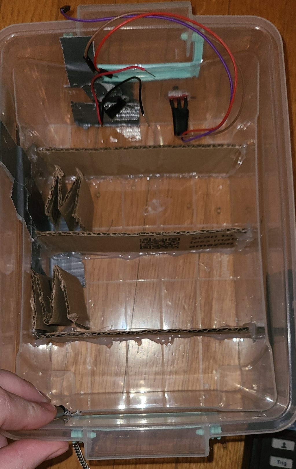
I attached the switch and speaker using a small amount of hot glue. I let the glue mostly cool before making contact with the electronics so as not to damage them. I put the breadboard on top of the risers and added a bit of cardboard on the side to prevent it from sliding around. I rested the breadboard on the risers instead of affixing it in case I wanted to take it out to work on it.
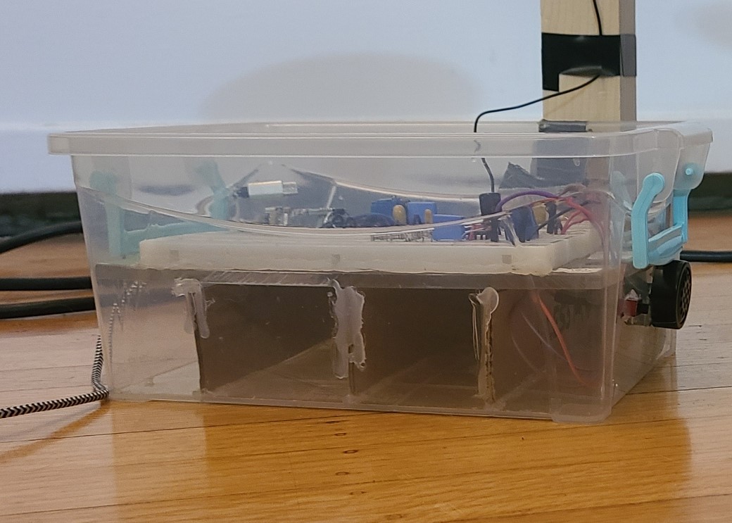
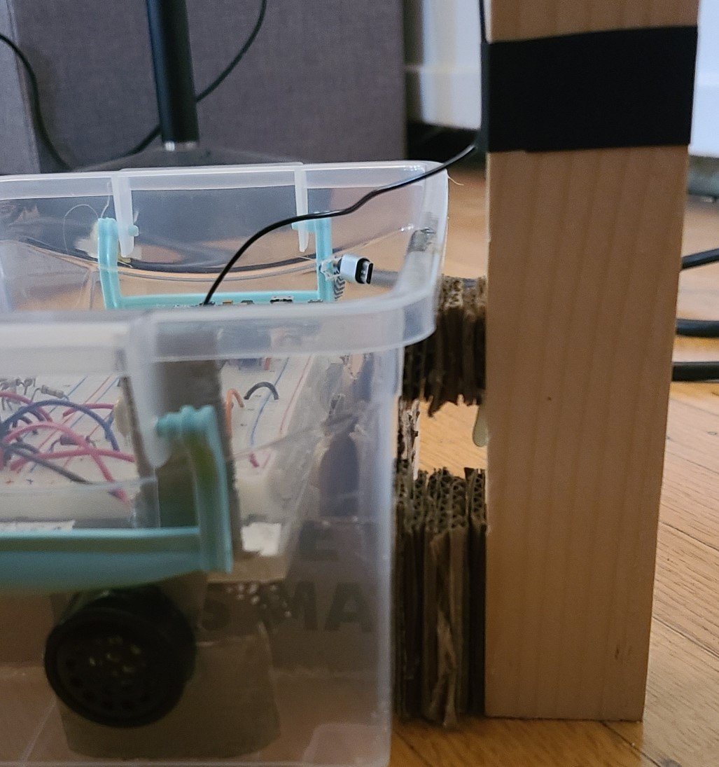
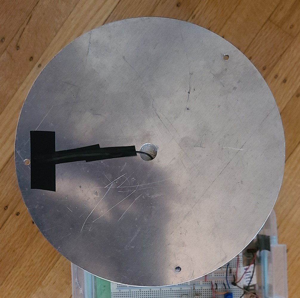
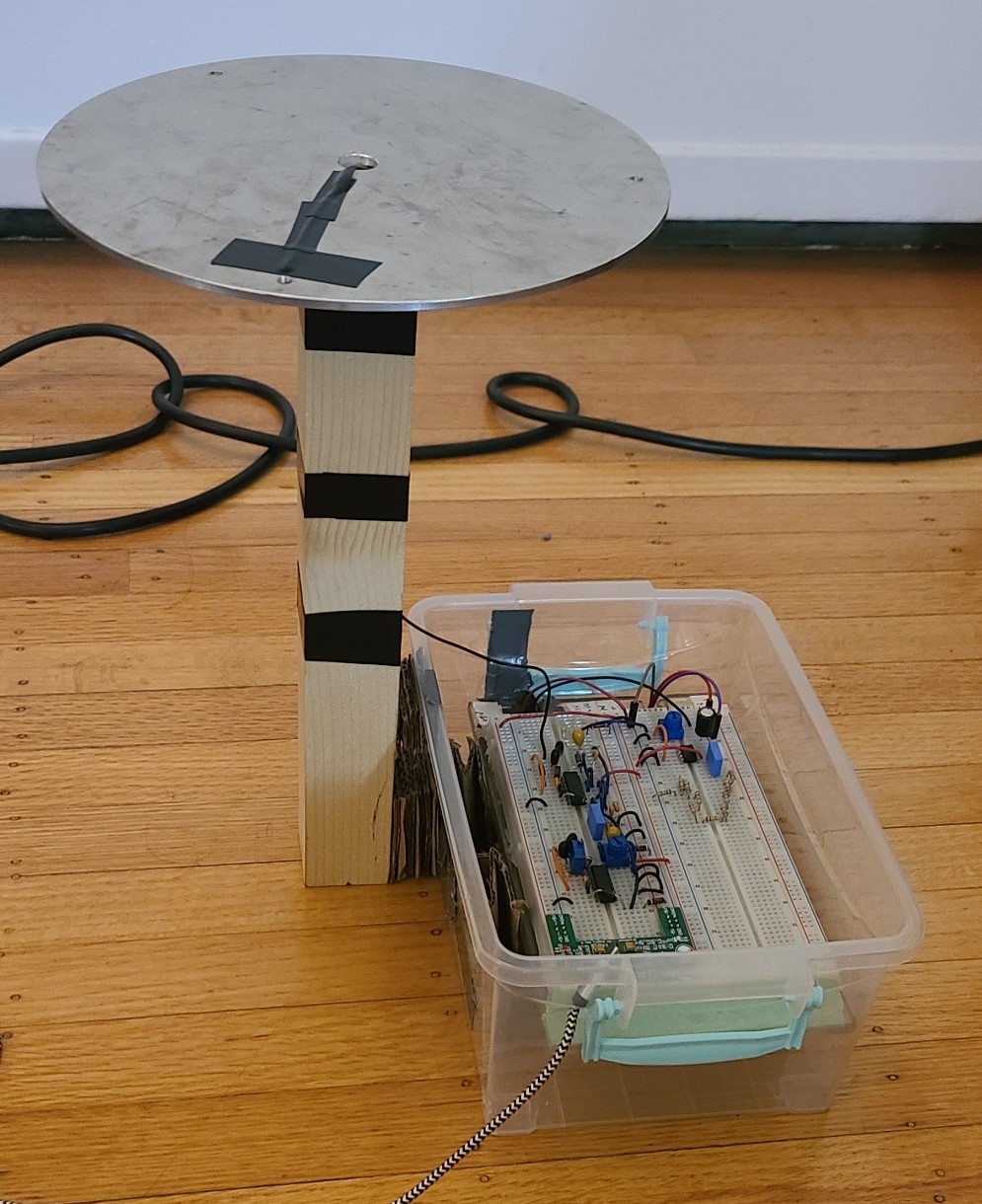
Now that the theremin is encased, you can build the antenna stand. I used a piece of 1.5" x 1.5" pine that was 12" long. I used hot glue to attach the antenna plate to the antenna stand. I then attached the antenna stand to the theremin casing. The walls of my casing were not straight vertically, so I used hot glue to attach some cardboard as a spacer to provide a vertical surface to attach the stand to. I also used hot glue to attach the stand to the spacers (see the picture below on the left). Depending on whether you are planning on moving your theremin and your casing requires spacers, you may want to make them out of something that doesn't tear as easily as cardboard. Make sure your antenna plate has a good connection with the antenna wire. I stripped about 2 inches of wire and taped it down to the antenna plate with electrical tape (see the picture on the right below).
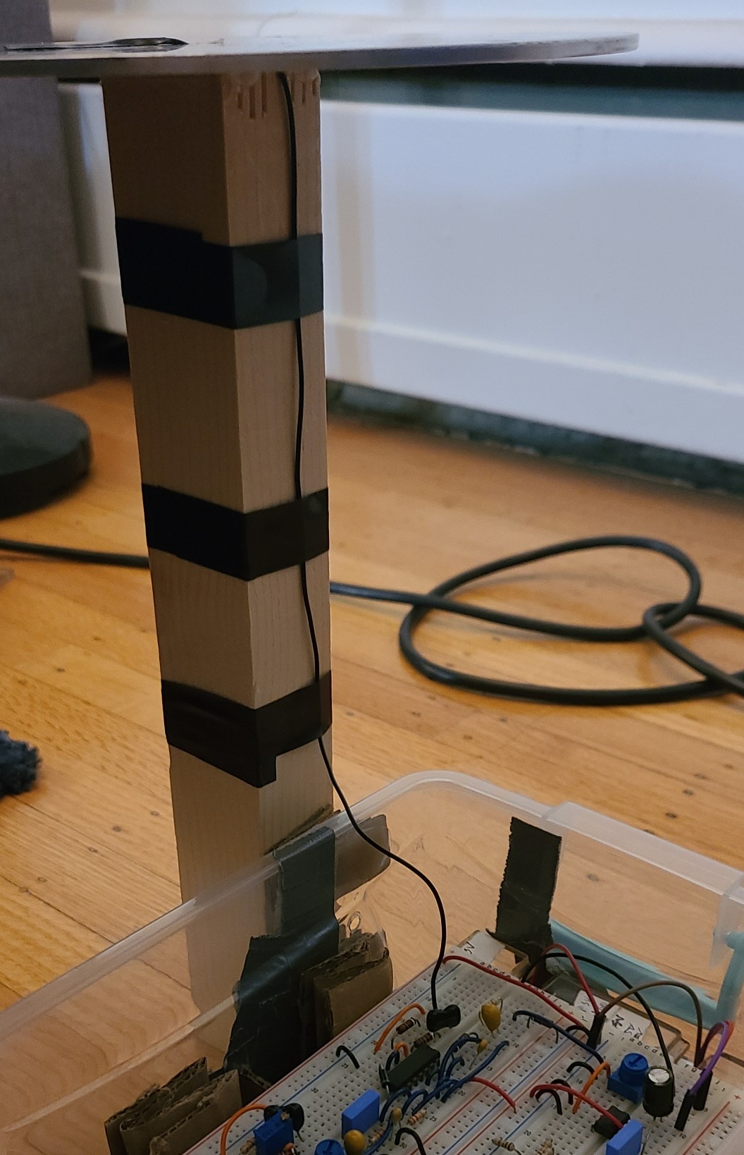
I used electrical tape to secure the wire down the length of the stand (see the picture below on the left). I trimmed the wire to the appropriate length and plugged it in to the circuit.
At this point, construction of the theremin is complete and you can start tuning it! I would recommend plugging it in and testing it right away in case anything was jostled out of position during the last few steps.
Tuning the Theremin:
To tune the theremin, make sure you are in a space where the antenna is clear from any nearby objects and especially anything conductive. Start by setting RV1 all the way counter-clockwise and setting RV2 to its middle position. Turn on the switch. Start turning RV1 clockwise with your hand or a screwdriver. You should hear a very high pitch that gradually gets lower until the sound stops (see the video on the left below - CAUTION: VERY LOUD AND HIGH-PITCHED). Once the sound stops, stop turning RV1. When you remove your hand and screwdriver, the sound may return. If it does, adjust RV2 until it stops again (see the video on the right below).
You can now bring your hand closer to the antenna plate and the pitch should change as you do so. You can also connect the oscilloscope and compare the frequency for the fixed and variable RC oscillators. When your hand is away from the antenna, their frequencies should be the same (see the photo on the left below). Now that you have a base line for tuning, you can try a few different combinations of positions for the variable resistors RV1, RV2, and RV3 to see if you can improve the sound or sensing distance. I found the best sound and sensing distance was when RV3 was in its middle position and RV2 was slightly clockwise of the position taken during initial tuning - there was a sound when my hand was outside the sensing range, but the overall sound was better. You can plug in the oscilloscope to the output of the mixer and amplifier as well. You should see the frequency of the output waves change appreciably as you bring your hand toward and away from the antenna plate (see the video on the right below). Congratulations, your pitch-control theremin is complete!
Presentation
The presentation takes about 1 hour including time for questions and for students to try the theremin. The presentation consists of a slide deck and a physical demonstration of the circuits and theremin. There are some brief speaker notes accompanying the slides. Please see the speaker notes for sources for the images used in the presentation slides. Download slides here.
Since some concepts may be beyond the students' current knowledge, concepts are explained throughout the presentation in as much detail as is necessary with little prior knowledge assumed. To facilitate comprehension and engagement, there are polling questions throughout the slides. These questions should be asked to the class and collaboration should be encouraged. I used the free version of a service called "Socrative" (https://www.socrative.com/) to collect answers to the questions. There are various similar services available, or you could just request verbal responses.
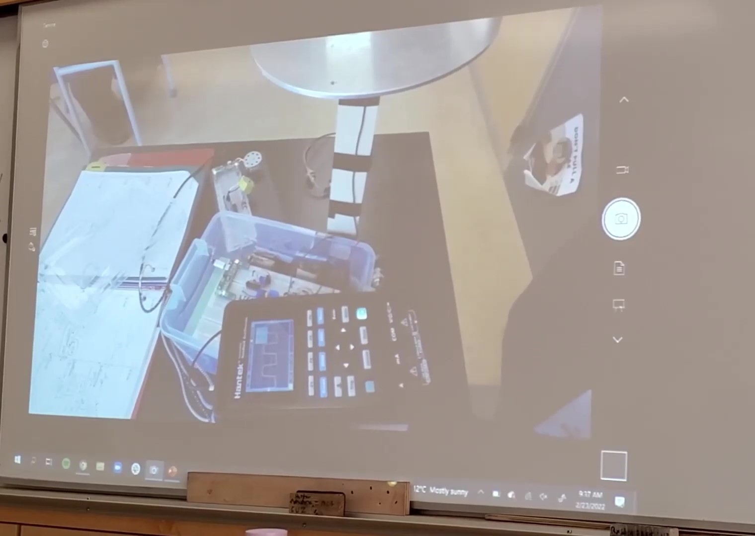
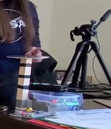
I used a webcam on a tripod to film the circuits during my demo. I connected the webcam to my computer so I could stream the video of the circuits through the projector to the whiteboard. You could also put the circuits under a document camera to project the circuits during the demo. Some pictures of my set up are below.
Throughout the slides, there are indications for where to include the physical demonstrations. The physical demo is split into the following 3 parts.
Demo Part 1: Fixed RC Oscillator
For this part, use the simple RC oscillator. Have students predict what they will see on the oscilloscope based on what they have just learned from the slide presentation. Connect the oscilloscope between the capacitor and the output to 1B on the hex inverter. Show the square wave output.
Demo Part 2: Variable RC Oscillator
For this part, use the simple RC oscillator again. Explain that the variable capacitor has two plates inside and when you spin the dial, the plates move apart or together. Ask what happens to the capacitance when the distance between the plates changes. Attach the variable capacitor and the oscilloscope. Have students predict what they will see on the oscilloscope based on what they have just learned from the slide presentation. In particular, have them predict what will happen when the capacitance is varied. Show the square wave output and how the frequency changes when the capacitance is varied.
Demo Part 3: Theremin
For this part, use the complete theremin. Start with the switch off and plug the oscilloscope into the fixed and variable RC oscillators. Predict what the scope should show. Compare the frequency of the output from the two RC oscillators.
Next, plug in the oscilloscope to the output of the mixer and turn the switch on. Predict what the scope should show. How does the frequency compare to the RC oscillators? When you move your hand near the antenna plate, how does the frequency change?
After the mixer, plug in the oscilloscope to the output of the amplifier and turn the switch on. Predict what the scope should show. How does the frequency compare to the RC oscillators and mixer? How does the amplitude compare to the mixer? When you move your hand near the antenna plate, how does the frequency change? Does the amplitude change?
At this point, you can play the theremin some more (I just moved my hand gradually closer and further away to "play" it, but you could try to actually make a song). Invite the audience up to try it themselves! I hope you enjoyed this project! I found it challenging, but very fun and rewarding. Enjoy your theremin!Contact
For any questions or comments, please feel free to contact me by email at kfdeane@gmail.com.
For more information about the PHYS 420 course and other demo ideas, visit the course resource page.