Demo 3: Quartz Oscillator Clock Circuit
Physics Concepts
- Basic Circuits
- Simple Harmonic Oscillators
- Piezoelectrics
- Programming
Required Materials
| Material | Amount | Notes |
|---|---|---|
| Laptop | 1 | You will also need the free Arduino IDE software found HERE |
| Arduino Uno | 1 | You will also need the USB Cable for the Arduino to connect to your computer |
| Half-Size Breadboard | 2 | You will need two separate breadboards since each will need its own power supply |
| 5V Breadboard Power Supply | 1 | |
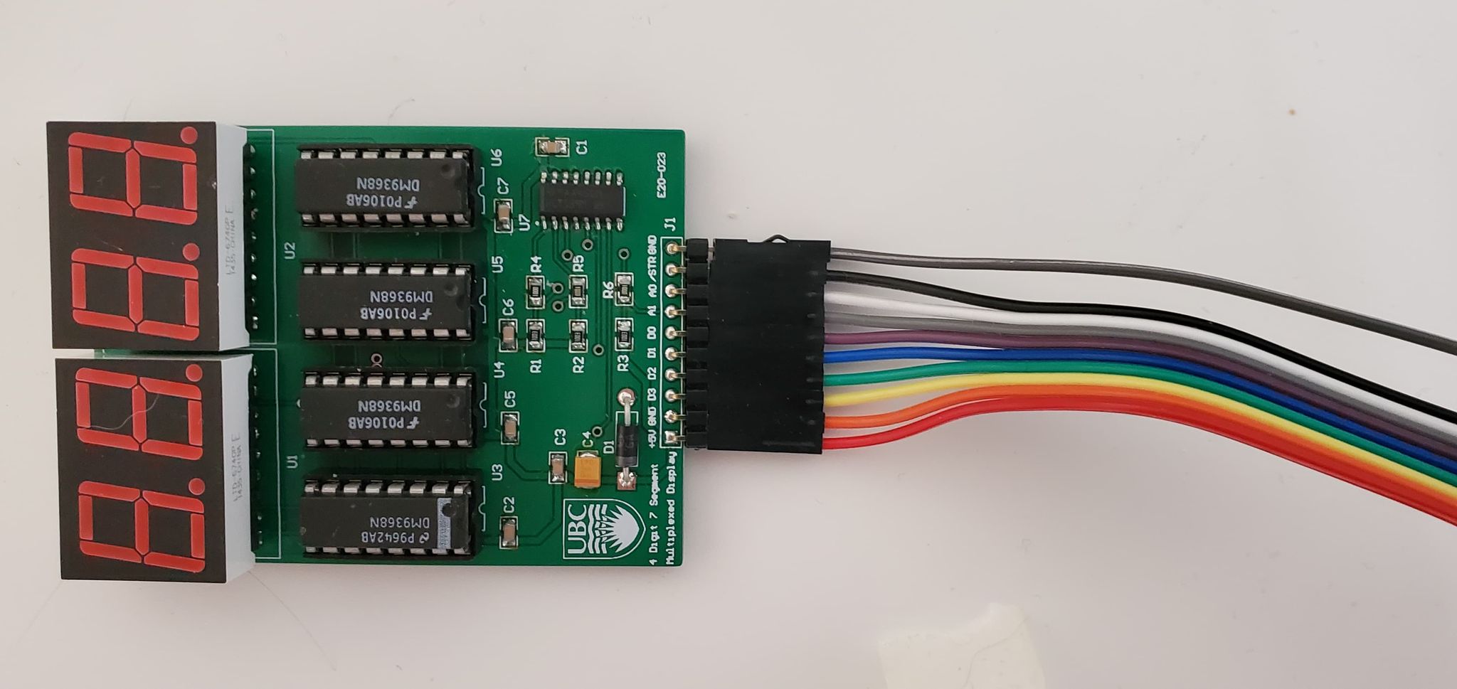
| 4-Digit Seven Segment Display Module | 1 | |
| Alligator Clips | 2 | |
| F-M Jumper Cables | 10 | |
| M-M Jumper Cables | 3 | |
| Solid Core Wire | 2 ft | |
| Wire Cutters/Strippers | 1 | |
| SN74LS04 Integrated Circuit | 1 | The Data Sheet for this part can be found HERE |
| 560 Ohm Resistor | 1 | You can also use multiple resistors in series adding to 560 Ohms |
| 1.8 kOhm Resistor | 1 | You can also use multiple resistors in series adding to 1.8 kOhms |
| 220 Ohm Resistors | 2 | You can also use multiple resistors in series adding to 220 Ohms but will need to do so twice |
| 10 MHz Quartz Crystal | 1 | |
| Oscilloscope w/ Circuit Probes | 1 | This is optional but useful for debugging the circuit and for showing what the circuit does to the class |
Construction
Oscillator Circuit
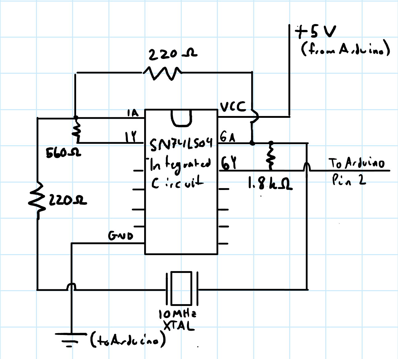
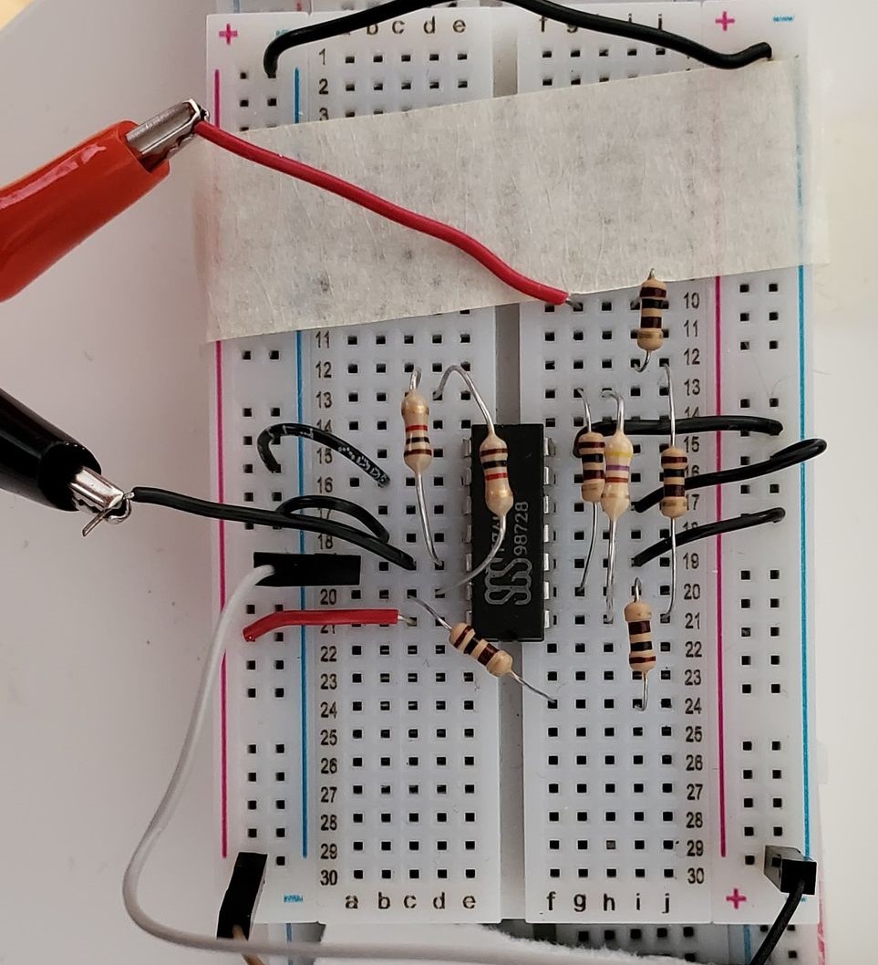
- Take one of the breadboards and plug in the integrated circuit along the centre of the board so half the pins are on one side of the divider and half are on the other side and orient the chip such that the notch in the black part faces the top of the board
- Note: I accidentally build the circuit with the board upside-down thus the photo below reflects this. The circuit itself, however, is unaffected
- Using a segment of solid-core wire, connect the VCC pin to the positive track of the breadboard
- Using a segment of solid-core wire, connect the GND pin to the negative track of the breadboard
- Using a 560 Ohm resistor, connect the 1A pin to the 1Y pin of the integrated circuit (IC)
- Note: If you are using a combination of resistors in series to create a 560 Ohm resistor, make sure you do not accidentally plug them into the same row as any of the other pins on the IC other than the first terminal of the first resistor in line with 1A and the last terminal of the last resistor in line with 1Y
- Using a 1.8 kOhm resistor, connect the 6A pin to the 6Y pin of the IC
- Note: If you are using a combination of resistors in series to create a 1.8 kOhm resistor, make sure you do not accidentally plug them into the same row as any of the other pins on the IC other than the first terminal of the first resistor in line with 6A and the last terminal of the last resistor in line with 6Y
- Using a 220 Ohm resistor, connect the 1Y pin to the 6A pin of the IC
- Note: If you are using a combination of resistors in series to create a 220 Ohm resistor, make sure you do not accidentally plug them into the same row as any of the other pins on the IC other than the first terminal of the first resistor in line with 1Y and the last terminal of the last resistor in line with 6A
- Using another 220 Ohm resistor, connect the 1A terminal of the IC to an empty row of the breadboard
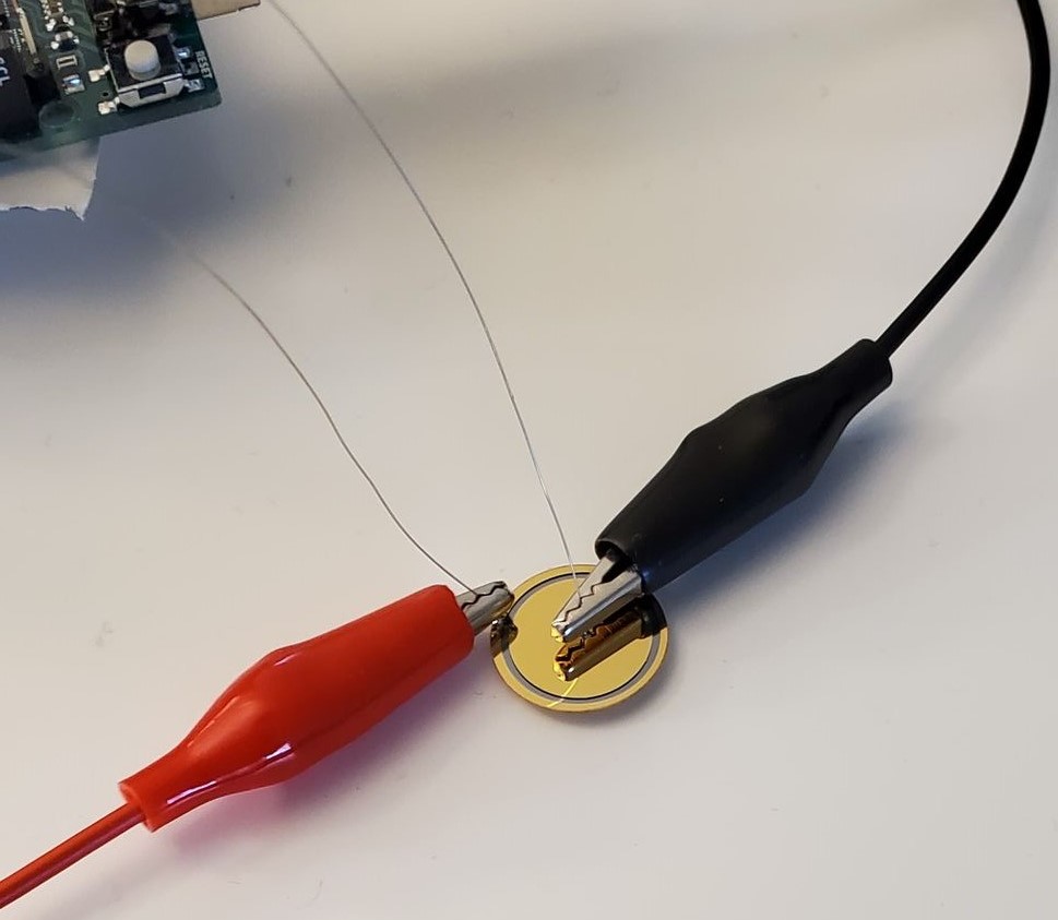
- Next, using alligator clips, connect a piece of solid core to one end of the alligator clip and plug it into the same row as the open end of the 220 Ohm resistor you just placed and the other to one of the leads from the quartz crystal
- Connect the other lead of the quartz crystal via alligator clip and solid-core wire to the 6Y terminal of the IC
- Using solid core wire, connect all other pins on the IC to ground
- This is to reduce noise in your circuit as a whole
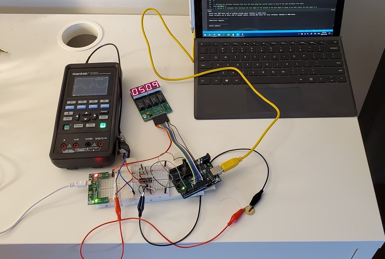
- Once you have done this you should have a circuit that looks something something like the photo below
- Note: The red and black alligator clips go to the leads on the quartz crystal shown in the image for Step 9
- Note: In the image below, the white, black, and brown jumper cables connected to the breadboard go to the Arduino as described in the steps below
Setting Up the Arduino
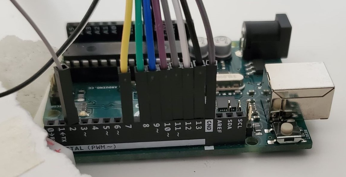
- Take the Arduino and connect the Arduino pins to your seven-segment display using the F-M jumper cables as follows
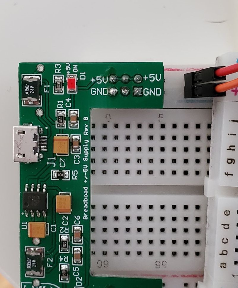
- Connect your power supply to the second breadboard
- Connect the 5V terminal of the seven-segment to the positive track of the breadboard using a F-M jumper cable (this should be connected to the +5V terminal of the power supply)
- Connect the other GND terminal of the seven-segment to the negative track of the breadboard using a F-M jumper cable (This should be connected to the GND terminal of the power supply)
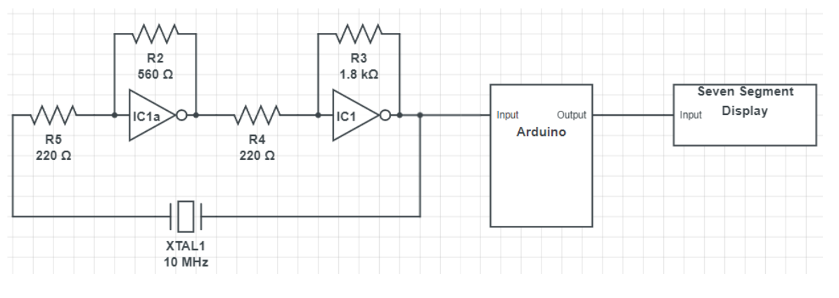
- Using M-M jumper cables, connect the following pins from the Arduino to the oscillator circuit breadboard (These are also shown in the circuit image above)
- Connect the USB to the Arduino and plug it into your laptop
- Open the Arduino IDE and download the code found HERE and open it in the IDE
- If you are having issues with the above download, you can copy and paste the code from the txt file found HERE into the IDE
- Upload the code to your Arduino by ensuring your Arduino is selected and pressing the upload button
- If you are having issues with uploading to your Arduino, THIS is a good resource for troubleshooting (apologies for the webpage name)
- Ensure the power supply for the seven-segment display is connected to power
- The Arduino should now be acting as a timer that counts up and is accurate to within a few percent of a second
- If the Arduino is not counting up on the seven-segment, check that both the code and your wiring are correct
- If the clock is counting up but seems to be too fast or too slow, you can edit the variable counts as there may be more or less latency in your circuit than in mine depending on the quality of your materials
| Arduino Pin | Seven-Segment Pin |
|---|---|
| 7 | D3 |
| 8 | D2 |
| 9 | D1 |
| 10 | D0 |
| 11 | A1 |
| 12 | A0 |
| 13 | STR |
| GND | GND |
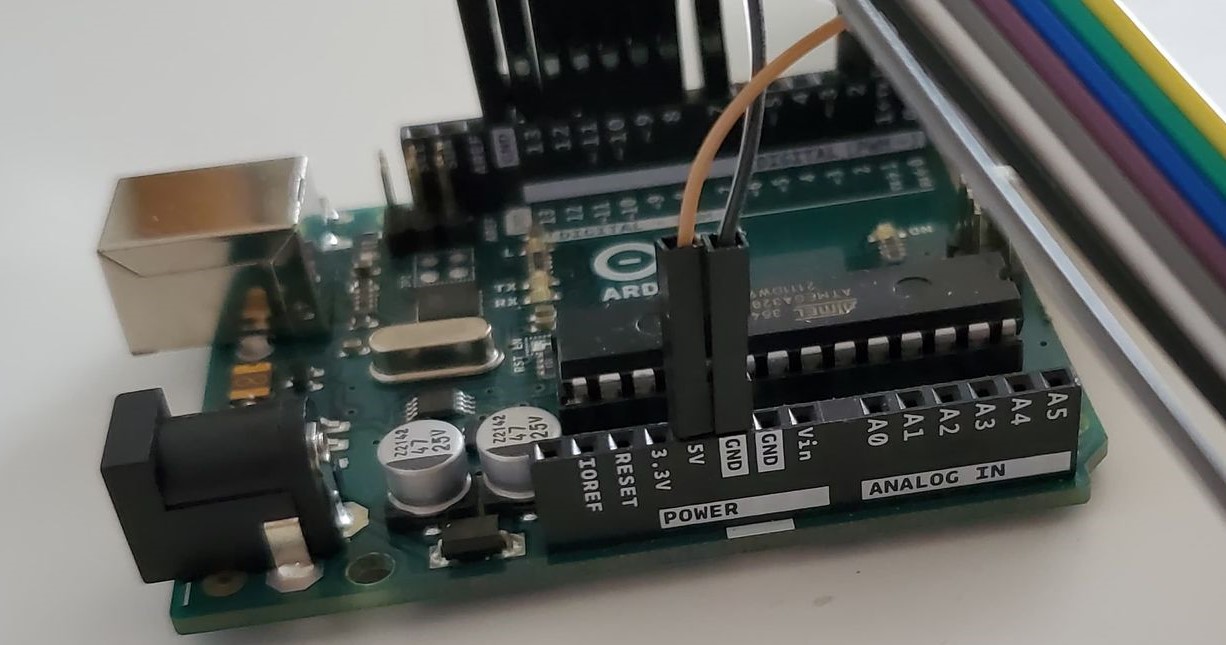
| Arduino Pin | Oscillator Circuit Location |
|---|---|
| 2 | Same row as pin 6Y on the IC |
| 5V | Positive track of breadboard |
| GND | Negative track of breadboard |
Using the Oscilloscope
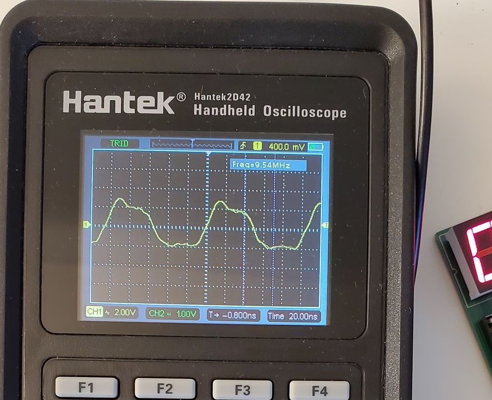
- Using solid-core to BNC probes on the oscilloscope, plug one probe into the negative track on the oscillator breadboard and the other probe into the same row as the 6Y terminal of the IC
- This should result in you seeing a square wave which is the output of the circuit at approximately 10 MHz
Running the Demo
- Discuss with the class what the circuit does
- The Arduino "kicks" the quartz crystal with a 5V pulse
- Due to piezoelectrics, this results in the crystal vibrating at its resonant frequency (10 MHz) and releasing a pulse back into the circuit
- This pulse travels to the first IC inverter and splits, one section going through the 560 Ohm resistor and one through the IC
- The part of the pulse going through the IC is inverted from high voltage to low voltage and the part of the pulse going through the resistor is left at high voltage
- The now half square wave of a low and a high voltage reach the next IC and resistor and perform the same operation resulting in a pattern of high and low signals in a square wave formation
- These square waves pass back into the crystal creating a feedback loop that kicks the crystal again and makes it continue outputting square waves at 10 MHz
- The Arduino is set to pick up each high voltage and count them and when it reaches the 10000 (or the number you have set due to latency) it counts 1 second and performs math to set the time and pass that time to the seven-segment display
- You can also show the square wave using the oscilloscope via an overhead projector so the students can see the waveform being created by the quartz crystal
Discussion Points
- Discuss the idea of how the circuit works with the students as above
- See if the students can think of any possible ways this circuit could go out of sync from actual time
Powered by w3.css